- Passive Thermal Solutions
- Active Thermal Management Solutions
- Embedded Computing Solutions
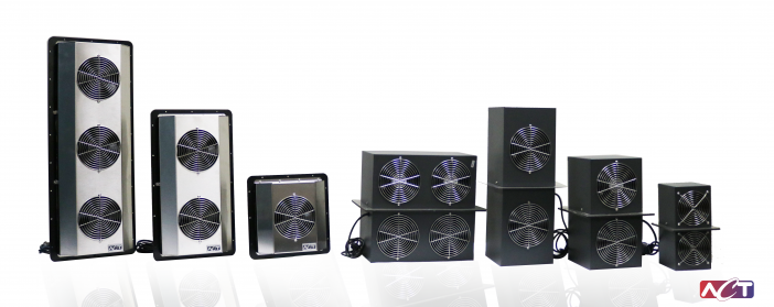
- Enclosure Cooling Products
- HVAC Energy Recovery
- Space Thermal Control
ACT’s enclosure cooling products effectively dissipate heat from sealed electrical and electronic enclosures operating in indoor, outdoor and other types of environments.
These products are applicable in diverse industries including Industrial Automation, Food Processing, Chemical, Petrochemical, Wastewater Treatment, and Telecommunications.
ACT offers a high level of technical support to automation & control systems integrators and OEM’s through our website selection tools, online ordering and direct field support from our factory and local technical representatives.
Explore Enclosure Cooling Products
When selecting a sealed enclosure cooling product, it’s important to consider factors such as the heat load,
enclosure size, environmental conditions, and power requirements to ensure proper cooling and
optimal performance of the enclosed electronics.
Coolers
Coolers
Coolers
Coolers

We have experienced engineers and full-service manufacturing operations to provide a cooling solution for your overheating cabinet, as well as provide superior customer service from the time of order through installation!