The patented Isothermal Card Edge ICE-Lok® is designed to enhance thermal performance for conduction-cooled embedded computing systems. Compared to conventional wedgelocks, the ICE-Lok® creates additional heat transfer paths from card to chassis, thereby reducing the thermal resistance.
The ICE-Lok® thermally enhanced Wedge lock, can be seamlessly integrated into standard VITA systems, enabling a longer lifetime and higher reliability for your critical components without costly board or chassis redesign.

ICE-Lok® Wedgelock Benefits for Embedded Computing

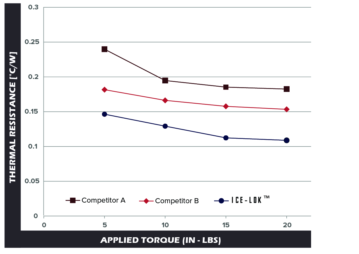
• 33%+ reduction in thermal resistance from equivalent size COTS wedgelocks, due to added heat transfer paths and surfaces
• Single screw access for easy board installation/removal
• Rugged design and construction as validated through shock/vibration testing and repeated installation cycles
• VITA 48.2 compliant
• Compatible with standard VITA 3U, 6U and 9U cards
• Superior clamping force
• Space VPX applicapable
Everything you need to know about thermally enhanced wedgelocks

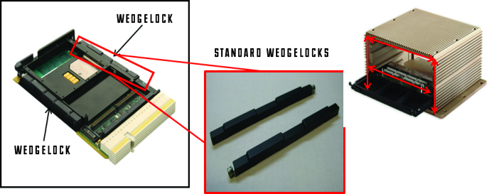
Wedgelocks are used when electronics cards must be easily replaceable. The wedgelock is a mechanical clamp that allows a card to be swapped quickly but has the drawback of being a relatively poor thermal conductor. As power per card continues to increase, a lower thermal resistance device is needed.
Yes. By lowering the thermal resistance by more than one-third, replacing a standard wedgelock with a 3/8” ICE-Lok®, component temperatures are lowered by 10°C at 100 W power input.
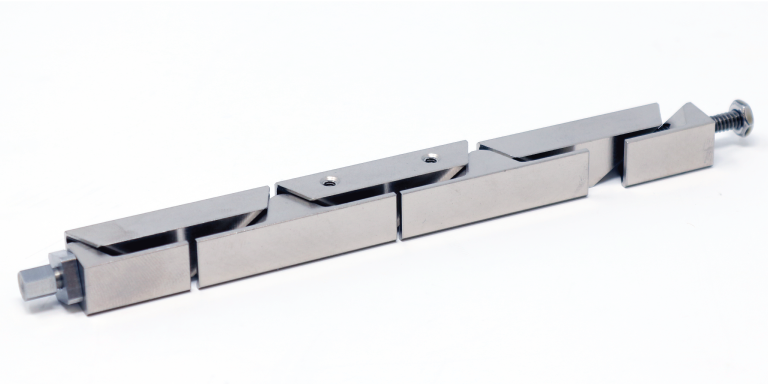
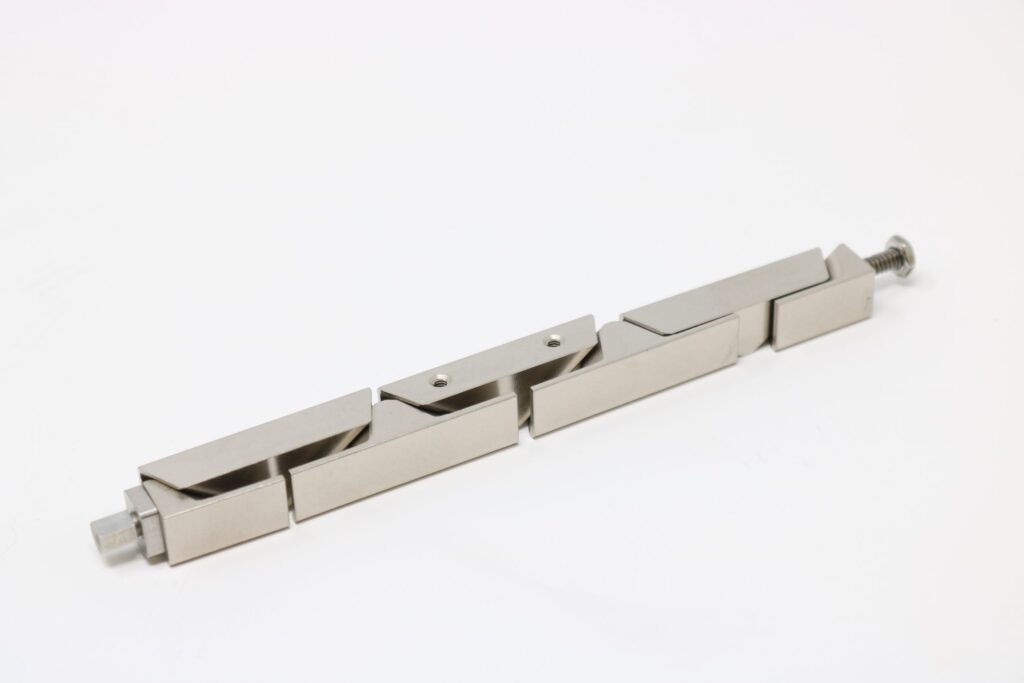
As shown in the photo on the right and Figure 1 below, a standard wedgelock has a series of trapezoidal-shaped wedges, with an internal screw. As the screw is tightened, the wedges are forced up and down, exerting pressure to clamp the card into the chassis.
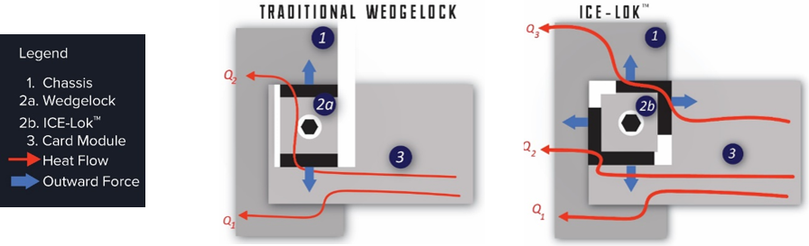
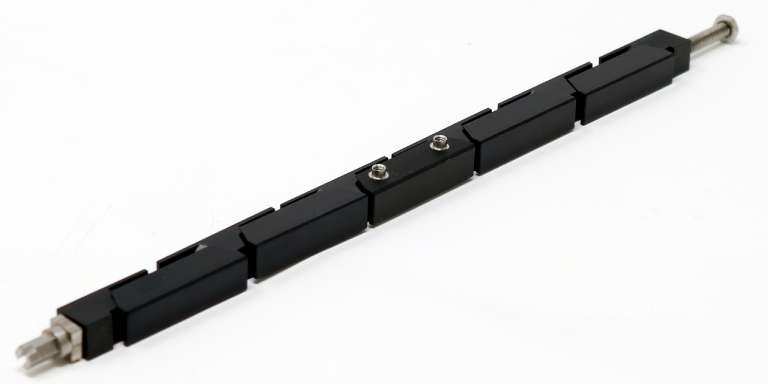
As shown in the photo to the right and described in the video below, the ICE-Lok® improves performance by increasing the surface area for heat transfer and maximizing contact pressure. The wedges are cut at a bias, so that the wedge can expand in two directions, allowing the ICE-Lok to contact all four sides of the thermal interface. An integral bracket also reduces thermal resistance.
The nut driver size is 1/8”.
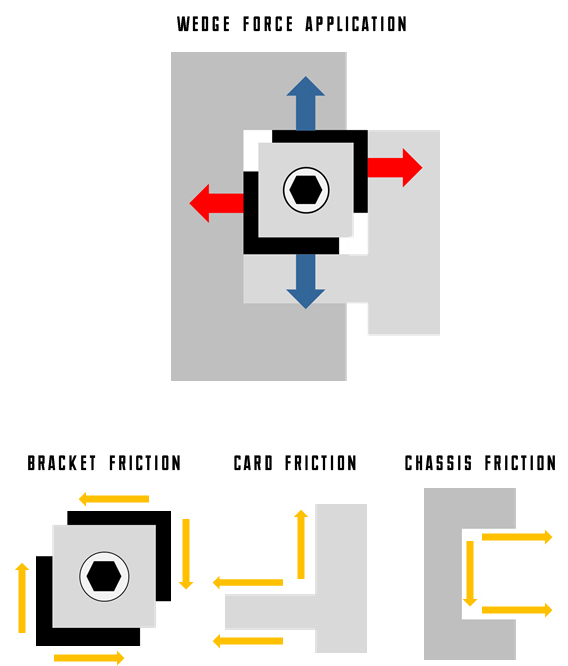
Chassis and/or card deformation is not a problem, since the wedges are designed to “Friction Lock”. The wedges do not apply forces on the chassis or card until the wedges fully contact all four faces. When considering a horizontal conduction card, the bias angle of the wedges is designed so that the friction forces of the vertical load is greater than horizontally. This generates a friction force greater than the horizontal force and prevents the ICE-Lok® from further movement in the horizontal direction. This results in no external deflection of the chassis or conduction card.
The mass of a single, 9 wedge 375 ICE-Lok® is approximately 47.5 grams. For each increment in length, the mass changes by approximately 11 grams (i.e. 11 wedge – 58.5 grams; 7 wedge – 36.5 grams).
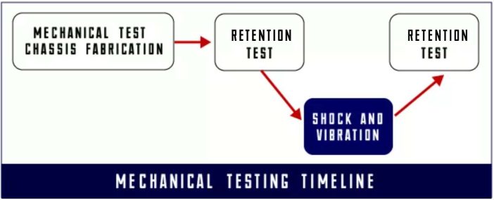
The qualification tests included both thermal and mechanical tests.
- ICE-Lok® Wedge lock Thermal Qualification Testing: The thermal testing procedure is shown in the figure below. In one set of tests, the thermal resistance was measured initially, and after each 20 card withdrawals/insertions. No appreciable change was measured.
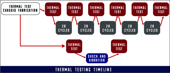
- In the other set of tests, the thermal resistance of the card was measured before and aftershock and vibration tests. The test conditions encompassed military aircraft, Delta IV, and Atlas V. No problems were observed.
In order to get the thermal benefits of the ICE-Lok®, both the Card Guides and Conductance Card need to make physical contact with the ICE-Lok, and by extension with each other.
ACT’s ICE-Loks® are designed to fit within chassis’ made to VITA standards. The downloads below can be used to help size the thickness of the conduction card flange. This way the card/ICE-Lok® assembly will be sure to fit within your chassis. However, the ICE-Lok® won’t expand indefinitely. Maximum limitations for each model can be found on the product data sheets and on each .STEP file below.
ICE-Lok’s® are available in standard in 1/4″ (250 series) with 7, 9, and 11 wedge configurations and 3/8″ (375 series) diameters with 5, 7, or 9 wedge configurations.

Now that you’ve learned what a wedge lock is and how they are used, it’s time to contact ACT for more information and a quote for improving your equipment’s thermal conductivity and efficiency. We will help you decide how best to meet your needs. We will provide you with everything you need to understand the cost of the ICE-Lok®solution as well as the options that will replace your current wedge lock.
Reduce your costs and improve the life and reliability of your equipment with a simple conversation designed to make your operations easier and affordable.
 Ice-Lok® Installation Instructions
 ICE-Lok® 250 Installation Instructions
ICE-Lok® Video Demonstration
ICE-Lok® 250 Installation Instructions
ICE-Lok® Video Demonstration
 Article: Characterizing Thermal Performance Through Card Retainers
Video: Friction Forces
Ice-lok® Spec Sheet
250 Series Ice-lok® Technical Data Sheet
375 Series Ice-lok® Technical Data Sheet
Space Solutions Overview
Article: Characterizing Thermal Performance Through Card Retainers
Video: Friction Forces
Ice-lok® Spec Sheet
250 Series Ice-lok® Technical Data Sheet
375 Series Ice-lok® Technical Data Sheet
Space Solutions Overview