- Heat Pipe Learning Center
- Pumped Two-Phase Learning Center
- PCM Learning Center
- HVAC Learning Center
- Videos
- eBooks
- Brochures
- Case Studies
- Webinars
Pumped single or two-phase cooling is generally used to remove and dissipate heat from high-power heat sources such as electronics and lasers, or when the thermal energy must be transferred a significant distance between the heat source and the heat sink. Pumped single-phase cooling is commonly used today in automotive systems and power electronics equipment, where the heat fluxes are relatively low and/or temperature uniformity is not required. In a pumped single-phase loop, the liquid coolant is pumped through a cold plate which is attached to the heat source being cooled. The temperature of the liquid coolant increases as it passes through the cold plate, absorbing and storing the heat in its sensible heat capacity.
What Are Pumped Two-Phase Cooling Systems?
When Properly Designed, Two-Phase Pumped Loops Can:
Benefits Over Single-Phase Cooling
Pumped two-phase systems require additional design since flow instabilities must be suppressed, and the system must accommodate both liquid and vapor flows. However, Pumped Two-Phase has the following benefits when compared with single-phase cooling.
Two-Phase Cooling System Layout
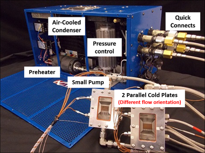
Figure 1. Stand-alone pumped two-phase cooling loop with quick-disconnects for cooling up to four cold plates.
Figure 2 (A) shows the test set-up for four cold plates, each of which can be heated independently. The individual cold plates are marked with blue, orange, yellow and red stickers. Note that the valves are used in this setup to provide a fixed pressure drop, adjusting them as flow conditions change is not necessary. Figure 2 (B) shows an individual cold plate in more detail.
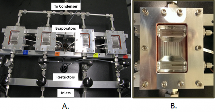
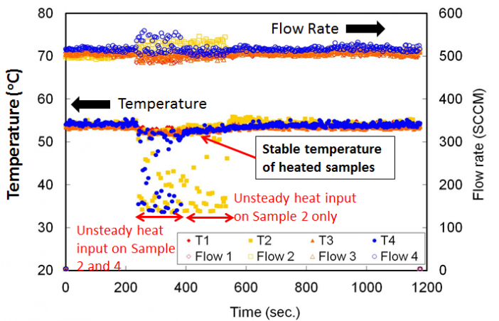
Figure 3. (A) Video showing two-phase cooling of 4 cold plates, with intermittent power. A dot shows when the heat is applied, and vanishes when the heat is turned off. (B) Turning off electrical power to some cold plates does not affect the temperature of the other cold plates.
Pumped Two-Phase COOLING Resource Links
Advancements in Pumped Two-Phase Cooling Technology
Webinars
Videos
Pumped Two-Phase FAQ
Now that you have the basics, we’re sure you have more complex questions. While some answers are specific to your needs and system requirements, these responses to standard questions will give you a better understanding of how these devices operate.

Yes. At ACT we handle all of the design and engineering and deliver complete, robust, turnkey Pumped Two Phase (P2P) solutions for military and commercial customers. The cold plates (evaporators) are always custom. For both military and commercial applications, ACT’s design philosophy is to use COTS (Commercial Off the Shelf) parts whenever feasible, to reduce costs. Our knowledgeable and experienced engineers work with our customers to identify their needs and then develop the complete system including: pumps, radiators, cold plates, fans, fluid lines, filters, and controls. Once the design is complete we will fabricate the entire system.
Many companies offer various components of complete thermal management systems, ACT does the entire system-level design and analysis required to make sure all of the individual components work together to meet your specific requirements. We specify and integrate all of the components to assure flow rates, pressure drops, serviceability, structural and thermal requirements are all met in a robust long life P2P cooling system.
A variety of materials can be used in a Pumped Two-Phase (P2P) cooling system. The main constraints are that the envelope must be compatible with the working fluid, and the envelope must be able to withstand the maximum saturation pressure. Refrigerant working fluids are compatible with aluminum, copper, steel, and stainless steel. Methanol can be used with steel, or stainless steel, but is not compatible with aluminum.
The fluid is chosen based on the operating and storage temperature ranges. Refrigerants, such as R134a are the most common working fluids. Benefits of these fluids include a low viscosity, low corrosion, and a low freezing temperature (-103°C R134a). Methanol (freezes at -97°C) has also been used in some pumped evaporative cooling systems. Water is typically not used, since it can damage the system when it freezes and expands. A “Figure of Merit” (boiling coefficient) for different refrigerants is shown in Figure 2. Refrigerant R134a has very favorable thermophysical properties, and is often used as the working fluid for many P2P applications.
The operating temperature range, depends on the working fluid chosen. The minimum operating temperature is set by the sonic velocity. As the vapor temperature in the evaporator is lowered, the vapor pressure drops. To carry a given amount of heat, the vapor velocity must increase, which in turn increases the pressure drop from the evaporator to the condenser. At low vapor pressures, compressible flow effects become important. If the vapor velocity at the minimum operating temperature is too high, a different fluid should be selected.
One maximum operating temperature limit is the critical temperature. As the critical point is approached, the latent heat goes to zero, so the heat transported by phase change (evaporation and condensation) also goes to zero. More practically, the maximum operating temperature is generally set by the maximum allowable working pressure in the system.
The storage temperature range of a Pumped Two-Phase (P2P) system depends on the working fluid selected. The minimum storage temperature is generally 10°C above the triple point, to avoid damage when the fluid freezes.
There are three constraints on the maximum storage temperature range:
- Typically set at 80°C or above (U.S. Department of Transportation shipping requirement).
- System must withstand the saturation pressure (and a safety factor) at the maximum pressure.
- Accumulator must be sized so that there is a minimum of 15 percent vapor volume at the maximum temperature. As the temperature increases, the liquid density decreases, and the liquid volume increases. If the entire system is full of liquid, it is no longer saturated, and the extremely high pressure can damage (or burst) the system. To avoid this, the accumulator is sized so that there is some vapor at the highest storage temperature.
Yes. The evaporators (cold plates) can operate in all orientations in any properly designed Pumped Two-Phase (P2P) system. Horizontal, vertical flow up, and vertical flow down have all been demonstrated by ACT simultaneously with different cold plates in a Pumped Two-Phase (P2P) system. Most ground-based P2P systems rely on gravity to separate the vapor and liquid in the accumulator. The hydrostatic head between the accumulator and pump provides Net Positive Suction Head (NPSH) at the pump inlet, preventing vapor lock. Ships can have a substantial side-to-side motion due to waves, but generally can rely on at least some hydrostatic head. However, military aircraft can have acceleration in any direction, while spacecraft operate in microgravity, with no hydrostatic head. With proper design, P2P cooling systems can operate on both aircraft and spacecraft.
Pumped Two-Phase cooling is ideal for situations where the radiators must be located remotely. Many applications benefit from having the heat rejected remotely so that the high-power thermal loads coming off of their equipment do not burden the existing HVAC or house coolant systems. It is feasible to locate your radiator many tens of meters away from the heat source using a Pumped Evaporative system.
The maximum heat flux depends on the working fluid, heated area, and any boiling enhancements in the channels. ACT has cooled 300-500 W/cm2 from the simple mini-channel evaporator shown in Figure 2. The Critical Heat Flux (CHF) is significantly increased with a simple sintered porous copper coating; see Figure 3.
There is no set limit to the number of cold plates that can be used. Some designs have dozens of individual cold plates. Note that the vertical distance between the top and bottom cold plate can affect the isothermality, since the bottom plate will have a higher saturation pressure (and saturation temperature) due to the hydrostatic head.
With proper design, heat can be switched on and off to some cold plates, while the temperature and cooling in the remaining cold plates are unaffected; see the video in Figure 6a. In this video four parallel evaporators are present and are somewhat randomly turned on an off. When a heat load is applied to an evaporator, a colored circle is shown and bubble generation resulting from boiling of the working fluid can be seen. Note that the outlet is at the top of the heat exchanger where the most vapor is seen, with the inlet at the bottom. When no heat is being applied, there is no colored circle and only liquid is present. The second heater from the right, with the yellow dot, is the one most frequently turned on/off. As shown in Figure 6b, the temperatures of the “on” cold plates were not affected by switching other plates on and off. This is accomplished by adding flow constrictors upstream of the individual cold plates, with ΔP’s significantly greater than the change in cold plate pressure drop for single versus two-phase flow. The video at the top of the page includes video of the test.
No. The best heat transfer and temperature uniformity over a cold plate are achieved with some liquid exiting the evaporator. For refrigerants, vapor qualities below 50 percent vapor are recommended. At higher vapor qualities, the heat transfer coefficient drops, harming isothermality. Excess liquid at the heat exchanger exit also simplifies the controls, since there is no possibility of a dryout, which would cause high temperatures and potential damage. The pumping power required to pump the excess liquid around the loop is minimal.
Yes. We have implemented solutions with quick disconnects to allow for the rapid removal or connection of cold plates from the primary loop. We have also used quick disconnects successfully with central distribution units (CDU’s) to attach and detach multiple cold plates in a common system.
The reliability of a pumped two phase cooling system is most often limited by the reliability of the pump that is used to circulate fluid. The pump life depends on many application-specific factors and the design of the pump itself. Please contact ACT’s experts so we can learn more about your application and better inform you about the design options which can meet your reliability goals.
Yes. We have developed several solutions that offer high voltage isolation through the use of dielectric and electrically isolating fluids, hoses and fittings. In fact, even in the unlikely event of a leak, the working fluids will not damage high voltage components.
Yes, we have developed cold plate and central distribution units (CDUs) for pumping. Typically, the CDUs take up 2U to 6U worth of space while the cold plates can be manufactured in 1U to 2U form factors. The CDUs are connected to the cold plates using quick disconnects.