
High Altitude Doesn’t Mean High Temperatures
The aviation industry faces a set of unique thermal challenges, often because of altitude changes and the vast temperature ranges. Let’s look at a few of those challenges and the thermal management strategies that can be implemented to overcome them.
Challenge 1: Ambient temperature range
For military environments—and especially for aircraft—it is typical to have a fairly wide temperature range that will influence the design. Encountered temperatures can fall below -25°C and can exceed 45°C. The temperature extremes to which the ambient sink is subjected are usually the design considerations that are levied on the mechanical engineers responsible for designing these avionics.
Challenge 2: Thermal resistance path
Critical to thermal success, it Is essential to ensure that all electronics have a low enough thermal resistance path to the edge to keep them under the maximum case temperature. In most applications, we’re designing to this maximum case temperature and modeling the junction-to-case resistance, which is well-known from the electronics manufacturer.
Example:
Maximum case temperature is 135° C
50° budget
Piercing temperature is 85°C
Explanation:
We’ll design to the maximum case temperature to make sure that the thermal resistance network from the case to that sink does not exceed the thermal budget. In this case, we’re saying a typical value is 135°C for the case temperature, and the piercing temperature is 85°C, resulting in a 50° budget.
Challenge 3: Altitude and Air Density
Another consideration unique to aircraft is altitude. In cases with high-altitude considerations, even lower temperature extremes may be encountered; residual power must be designed to make sure that the electronics don’t get too cold. And due to the low air density, it is likely necessary to design past convective heat transfer and look at the radiation side.
Enhancing Heat Transfer in Avionic Applications
Conduction-cooled systems are common for avionics as they are the easiest to design. If the power is low enough to get away with just metal conduction, that is the simplest and most economical of heat transfer methods. When that’s not possible, a few different options can be incorporated to enhance the conduction path:
- Unique metals, such as silver or diamond spreaders
- Heat pipe technology
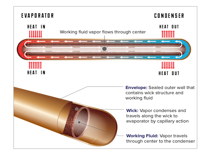
How do heat pipes work?
To give a brief overview, the heat pipe is coupled to the source electronics on one side and the heat sink on the other side. The working fluid vaporizes inside the heat pipe, creating a pressure gradient that pushes the vapor to wherever it’s cool in the system. When it reaches the side coupled to the heat sink, the vaporized working fluid gives up its latent heat, returning to a liquid; it is then absorbed into a wick structure that lines the inside of the pipe. That wick structure creates a passive capillary force, pumping the fluid back to the hotter source of the evaporator area. This is a completely passive process with no moving parts; it is a cycle created with the wick structure and the pressure fields. The result is a highly efficient heat transfer from Point A to Point B with less than a 5°C temperature difference.
Limitations and Design Criteria
There are certain limitations for heat pipes, and it is important to make sure that the heat pipes in a system have enough capacity to move the entire heat load. Considerations include:
- Temperature range – A variety of materials and working fluids are available, and they are selected to work within their optimal temperature ranges. In our example, copper-water heat pipes are used because the maximum case temperature, or sink temperature, is within the 85-135° C range. Water is the optimal fluid choice for that particular range, but other working fluid options may be utilized for different extremes in the temperature range.
- Vertical height – The vertical height of the heat pipe, and its orientation with respect to gravity, must be considered. Due to the capillary pumping action via the wick structure, the heat pipe’s operability may be affected if it needs to pump against gravity with the different pressure drops in the system. This is a design criterion that is especially critical for aircraft acceleration.
If different acceleration fields are applicable, it is necessary to account for those differences and design/model to those situations. In Figure 1, you can see that water heat pipes can move a significant amount of power above the 25-30°C range. Of course, water will begin freezing the closer to 0°C it gets. The heat pipe will survive freezing, but it won’t operate in a frozen state, though the electronics may not overheat during the frozen conditions anyway. This is based on the secondary conduction paths. As the temperature of the heat pipe rises (and approaches the key temperature range and the extremes), the heat pipe will start transferring power again.
Figure 2 displays the capacities of two systems with varying operations: one horizontal, and the other working a short distance against gravity. As shown, the capacity of the heat pipes in those systems changes based on the orientation with respect to gravity. To overcome the limitations of working against gravity, it is important to properly size the heat pipe diameters and incorporate enough heat pipes into the system to ensure that there is adequate capacity to move the entire heat load.
Practical Applications
One of the big challenges in avionics is the conduction limitation. The most common material for avionics is aluminum, which has roughly 167-170 W/mK thermal conductivity. Copper is usually the next choice in metals when aiming for a higher thermal conductivity; however, mass is always a major concern for avionic applications, and copper adds a significant amount of weight. Therefore, it is critical for engineers to design a thermal solution that balances the lightest weight and the best conductivity performance possible.
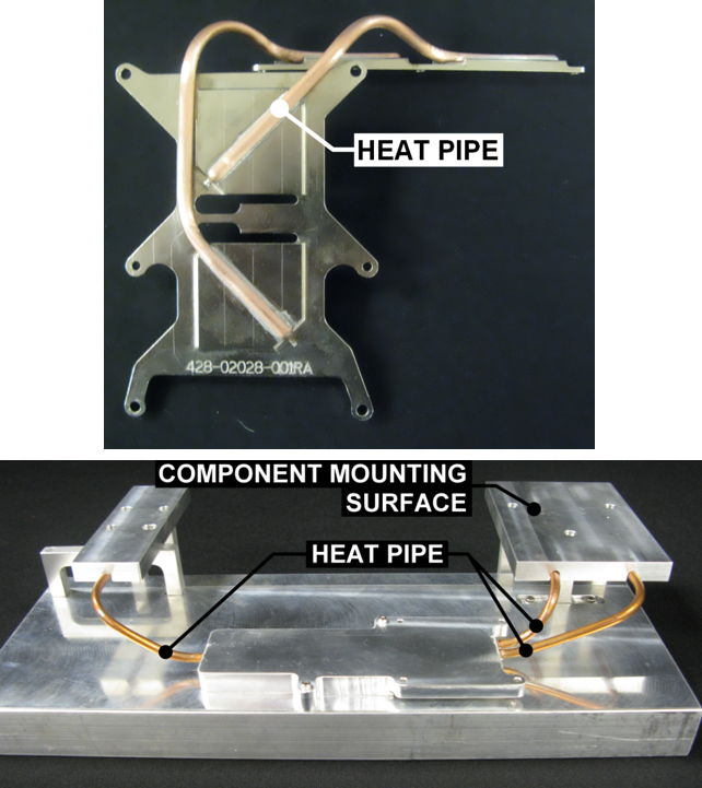
Spot Cooling Using Heat Pipes
Heat pipes are a popular method of spot cooling in avionics. An example is shown in Figure 3. The pictured system contains two main heat sources where the squares are touching the electronics; the heat spreader is bolted to the electronics, and the squares have
pedestals that contact the thermal interface that’s going to the electronics. The heat pipes take the heat from the two heat sources to a liquid cold rail, which can be seen in the horizontal section above the electronics. 25 watts per square inch is moved from the heat source to the sink with a 5°C temperature difference, reducing the thermal resistance.
The result is an increase in thermal efficiency. The case temperatures are reduced by the economical approach of the shorter thermal path, and heat pipes are inherently low-cost thanks to the simplicity of their construction and the ease of integration. They can also be very flexible, as they are easy to retrofit into designs and are applicable to all avionics MIL standards; heat pipes are shock and vibration tolerant and can survive freeze-thaw cycles amid low-temperature extremes.
Phase Change Material for Avionics
Phase change material (PCM) is used for thermal storage, the key consideration being the transient power of a system. In many cases, the aircraft electronics or systems will not be in operation at all times. In such cases where the systems run on significant duty cycles, one design possibility is to absorb the transient power during the periods in which the system is operating. That power can then dissipate during the off periods, allowing for a much smaller ultimate heat sink since the design is for the average power rather than the peak power. A PCM-integrated thermal storage device is utilized in these scenarios. These are passive solutions with no moving parts, resulting in a highly reliable and simplistic method of thermal storage.
Flight-critical avionics must be maintained below the design-to-temperature for mission success. It’s therefore critical to understand the system electronics and the heat sink conditions. The thermal solutions discussed in this piece are just a few of the passive tools that exist in the engineers’ toolbox for avionic applications.
Key Takeaways:
- Challenges in Avionics Cooling
- Enhancing Heat Transfer in Avionic Applications
- Practical Applications
- Heat pipes: for when conduction limitations are a big factor for the system.
- Phase change material: for when there’s transient operation (on-off cycles) in which the thermal loads can be absorbed.
- Understanding system-level design criteria: the ultimate sink conditions and where the design can take advantage of the system-level cooling solutions.
 Contact the ACT team today!