- HiK Plates/ Heat Pipe Assemblies
- Heat Pipes 101
- Different Types of Heat Pipes
- Heat Pipe Design Guide
- Pulsating Heat Pipes
- Vapor Chambers
- High Temperature Heat Pipes
ACT’s custom vapor chamber products are a result of the work of the R&D team’s beginning at the company’s inception in 2003 to refine the process for making high-quality custom vapor chambers.
You probably know that ACT offers technical and design services to provide you with a customized thermal management solution for your project. When you have a significant heat flux that warrants a custom vapor chamber, our skilled engineering teams are able to offer comprehensive thermal engineering services, covering everything from product conception to full-scale production. Our in-house manufacturing operations comply with the stringent ISO 9001:2015 and AS9100D quality standards.
What is a Vapor Chamber Assembly?
Vapor chamber heat spreaders are planar heat pipes that spread heat from concentrated heat source(s) to a large-area heat sink with effective thermal conductivities greatly exceeding those of copper. In the most basic configuration, the vapor chamber consists of a sealed container, a wick formed on the inside wall of the container, and a small amount of fluid that is in equilibrium with its own vapor. As the heat is applied to one side of the vapor chamber (evaporator), the working fluid vaporizes and the vapor spreads to the entire inner volume and condenses over a much larger surface (condenser). The condensate is returned to the evaporator via capillary forces developed in the wick.
Vapor Chambers are generally used for high heat flux applications, or when genuine two-dimensional spreading is required. Vapor chambers can accept heat from a high heat flux source, and spread the heat uniformly over a large area.
How Vapor Chamber Assemblies Help Solve Thermal Challenges
A concentrated high heat flux source is attached to one surface of the vapor chamber. The heat input vaporizes the working fluid. The vapor spreads through the entire inner volume and condenses along the much larger, cooler surface of the vapor chamber. The condensed liquid is transported back to the heat input area via the wick structure lining the vapor chamber inner wall. In some cases, the vapor chamber is referred to as a “heat flux transformer” because of its ability to convert higher heat fluxes into lower heat fluxes.
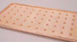
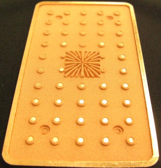
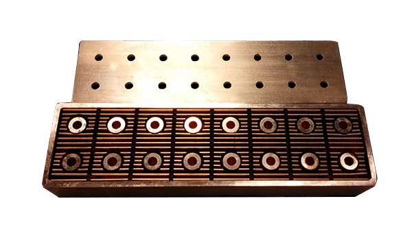
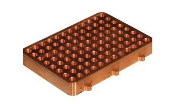
The photo to the right shows the internal structure of a typical copper/water vapor chamber. Arrays of internal posts provide structural support to accommodate the pressure difference across the vapor chamber envelope. A thin layer of wick lines the inner wall of the vapor chamber.
Vapor chambers may be used to cool a single microprocessor or multiple processors in a single plane. The vapor chamber can accept heat from each source and transfer the heat to an integrated air-cooled heat sink or water-cooled edge rails.
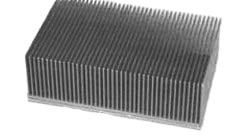
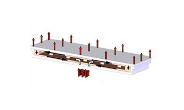
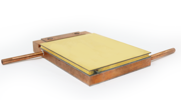
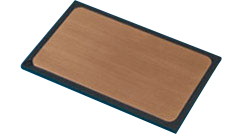
The photo to the right shows the components combined into a completed vapor chamber-heat sink assembly. The vapor chamber is bonded to the base of the heat sink. It accepts concentrated heat inputs and transfers the heat uniformly over the entire heat sink base. An isothermal heat sink base eliminates the temperature gradients due to conduction, improving the fin efficiency of the heat sink.
It should be noted that the effective thermal conductivity of a vapor chamber is dependent on the ratio of the heat removal area to the heat input area. This ratio is sometimes referred to as the area aspect ratio. The effective thermal conductivity of the vapor chamber increases with the area aspect ratio. Typical effective thermal conductivities range from 5,000 to 200,000W/m-K.
ACT’s vapor chamber product specifications
| Product Specifications | |
| Materials | Copper/Water |
| Planar dimensions | Scalable to 10″ x 20″ |
| Thickness | 0.125″ to 0.200″ |
| Heat Flux | > 100 W/cm2 |
| Thermal Resistance | < 0.08°C/W |
Low CTE, High Heat Flux, High Power, Low Resistance Vapor Chambers or Thermal Ground Plane
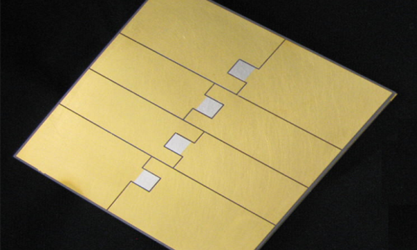
Direct Die Attach with high heat flux and high power capabilities
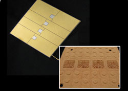
To meet the increasing demand for improved thermal management solutions, ACT has advanced Vapor Chamber Products available. These devices, also referred to as Thermal Ground Plane (TGP), offer high heat loading, with heat fluxes above 700 W/cm² over a 1 cm² area and total power up to 2,000W at a heat flux of 500 W/cm². These new Vapor Chambers/ Thermal Ground Planes are constructed with aluminum nitride ceramic plates covered with direct bond copper (DBC). This structure enables direct attachment to high-powered silicon, gallium arsenide, and gallium nitride microelectronics chips. This type of vapor chamber is ideal for thermal management in laser and other high-powered electronic cooling applications. Vapor chamber sizes are customizable. To date, sizes up to 10cm x10cm have been manufactured.
Performance features of vapor chamber assemblies include:
- High Power: > 2000W with 4cm² Heat Input (>500 W/cm²)
- High Heat Flux: > 700W/cm² with 1cm² Heat Input
- Low Evaporator Resistance: 0.05 to 0.1 °C/W-cm²
- Low CTE -Aluminum Nitride Ceramic with Direct Bond Copper – Approximately 5.5 ppm/°C
- Direct Die Attach – Direct Bond Copper Can be Etched for Electrical Circuitry, Gold Plated, Gold/Tin Deposited for Direct Solder Attach – Demonstrated on TGP Prototype

