- HiK Plates/ Heat Pipe Assemblies
- Heat Pipes 101
- Different Types of Heat Pipes
- Heat Pipe Design Guide
- Pulsating Heat Pipes
- Vapor Chambers
- High Temperature Heat Pipes
Heat Pipes are one of the most efficient ways to move heat, or thermal energy, from one point to another. These two-phase systems are typically used to cool areas or materials, even in outer space. Heat pipes were first developed for use by Los Alamos National Laboratory to supply heat to and remove waste heat from energy conversion systems.
Today, heat pipes are used in a variety of cooling applications from space to medical devices and power electronics cooling to aircraft and more! If you’re unsure if heat pipes are an ideal thermal solution for your project, contact us to discuss your application and our engineers can determine the best path forward.
How do They Work?
A heat pipe consists of a working fluid, a wick structure, and a vacuum-tight containment unit (envelope). The heat input vaporizes the working fluid in liquid form at the wick surface in the evaporator section.
Vapor and its associated latent heat flow toward the colder condenser section, where it condenses, giving up the latent heat. Capillary action then moves the condensed liquid back to the evaporator through the wick structure. Essentially, this operates in the same way as to how a sponge soaks up water.
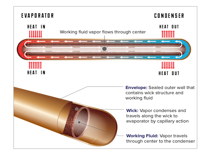
Phase-change processes and the two-phase flow circulation in the heat pipe will continue as long as there is a large enough temperature difference between the evaporator and condenser sections. The fluid stops moving if the overall temperature is uniform, but starts back up again as soon as a temperature difference exists. No power source (other than heat) is needed.
In some cases, when the heated section is below the cooled section, gravity is used to return the liquid to the evaporator. However, a wick is required when the evaporator is above the condenser on earth. A wick is also used for liquid return if there is no gravity, such as in NASA’s microgravity applications.
Every Heat Pipe Has Three Components
- Heat pipe working fluid, the fluid material within the envelope which transfers heat by evaporation and condensation.
- Heat pipe envelope, the outer “shell” material which provides a leak-tight pressure vessel to contain the working fluid.
- Heat pipe wick, the material within the envelope used to return liquid from the condenser to the evaporator using capillary forces.
Copper/Water Heat Pipes are the most commonly used fluid/envelope pair for electronics cooling.
- Gas Generation (Most Common)
- Corrosion
- Materials Transport
Heat Pipe Fluids
Selecting A Heat Pipe Working Fluid
Evaporation and condensation of the working fluid are what give heat pipes their high effective thermal conductivity, which can be as high as 100,000 W/m K. During heat pipe operation, the working fluid is vaporized in the evaporator and then condensed in the condenser, thus transferring heat.
The first step in selecting a heat pipe working fluid and envelope/wick material is to determine the operating temperature range. For a heat pipe to operate, it must be at saturated conditions, where the heat pipe contains both liquid and vapor. The practical operating temperature range for a copper/water heat pipe is roughly 25° to 150°C.
Learn more about theoretical and practical temperature ranges for heat pipes below.
Heat Pipe Fluid Selection FAQs

The merit number determines the maximum possible heat transport using the heat pipe. It is used to help determine the appropriate working fluid.
The merit number is derived by neglecting gravity and assuming that the liquid flow (Darcy’s law) accounts for all of the pressure drop in the heat pipe. Liquid pressure drop can be calculated according to:

where:
| ΔP_l | Liquid pressure drop in the wick |
| ṁ | Mass flow rate of the liquid |
| L_Effective | The effective length of the heat pipe |
| k_wick | The permeability of the wick |
| A_wick | Cross-sectional area of the wick |
| rc | Radius of curvature at liquid/vapor interface |
| Q | Volumetric flow rate |
Rearranging these equations, we find:

Separating the geometry-specific variables (first term) from fluid property variables (second term) reveals the merit number.
Heat pipes fluids are ranked by the Merit Number formula:
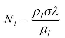
where:
ρl Liquid density
σ Surface tension
λ Latent heat
μl Liquid viscosity
High liquid density and high latent heat reduce the fluid flow required to transport a given power, while high surface tension increases the pumping capability. A low liquid viscosity reduces the liquid pressure drop for a given power. The Merit number is derived below.
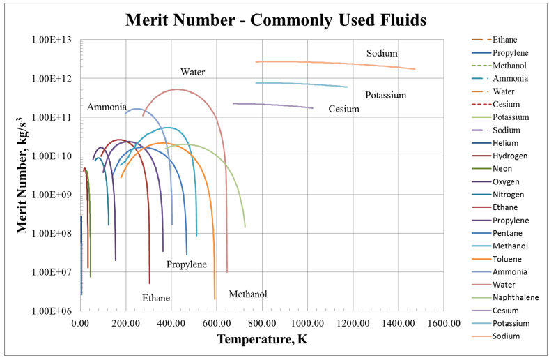
Figure 1. Merit Number for Commonly Used Heat Pipe Working Fluids.
The Merit number as a function of temperature is shown in Figure 1 for a number of typical heat pipe working fluids. From the figure, it is very clear why water is chosen as the heat pipe working fluid whenever possible. Its Merit number is ~10 times higher than everything else except the liquid metals, meaning that it will carry ten times more power (in the proper temperature range) than other working fluids.
Ammonia is chosen for spacecraft heat pipes since it has the highest Merit number (roughly 3 times less than water) in their typical operating temperature range. Methanol is generally the working fluid of choice when ammonia and water are not suitable, since it has the third-highest Merit number near ambient conditions.

Working Fluid and Envelope Compatibility Table
(includes Practical Temperature Limits)
Since heat pipes were rediscovered by George Grover in 1963, extensive life tests have been conducted to determine compatible envelope/fluid pairs, and a large number have been found. Some of these life tests have been conducted for decades. As mentioned above, most heat pipes are fabricated for electronics cooling, and are either copper/water or copper/methanol. Most spacecraft heat pipes are aluminum/ammonia, most heat pipes for HVAC applications are copper/R134a or steel/R134a, and most high-temperature heat pipes are superalloy/alkali metal. These envelope/fluid pairs cover the vast majority of heat pipes used today.
This section discusses the compatibility for these envelope/fluid pairs, and other pairs used in special circumstances. The table below lists most envelope/fluid pairs used today, as well as some envelopes that are known to be incompatible.
An estimated upper and lower fluid temperature range is also shown. In most cases, the lower limit is set by the sonic limit, while the upper limit is set by the maximum vapor pressure that can be contained with a reasonable envelope wall thickness. Heat pipes can be built that operate at lower temperatures with a large diameter to maximize the sonic limit, theoretically down to the triple point). Heat pipes can also be built that operate at higher temperatures, theoretically up to the critical point, but will require a thicker envelope to withstand the vapor pressure, and will have a reduced capillary limit.
The practical upper temperature limit for copper/water heat pipes is set by the vapor pressure at around 150°C; Monel or titanium are used at higher temperatures. It is very important to note that the table lists the generic type of material, such as Monel or Superalloy. In many cases, only some alloys are known to be compatible, while others have not been tested. Only some stainless steels are suitable for cryogenic heat pipes, since other steels become very brittle at low temperature.
The upper temperature limits for cesium, potassium, and NaK are set by ranking the properties of suitable alkali metals at a given temperature. For example, cesium is not normally used at higher temperatures than 600º, since potassium is a superior working fluid. This can be seen graphically in Figure 1, which compares heat pipe power versus temperature for identical heat pipes using either cesium or potassium as the working fluid. On the left side of the graph, the maximum heat pipe power is set by the sonic limit (the roughly parabolic part of the curve), while on the right side of the graph, the maximum power is set by the capillary limit (the roughly flat part of the curve). At lower temperatures, more power can be carried with cesium, since it has a higher vapor density (and higher sonic limit) at any given temperature. Once the temperature is increased above roughly 500°C, the potassium heat pipe carries more power (for this particular design). This is the reason that the table above states that cesium is not normally used above 600°C.
|
Operating Min Temp., °C |
Operating Max Temp., °C |
Working Fluid |
Compatible Envelope Materials |
Incompatible |
Comments |
|
-271 |
-269 |
Helium |
Stainless Steel, Titanium |
||
|
-258 |
-243 |
Hydrogen |
Stainless Steel |
||
|
-246 |
-234 |
Neon |
Stainless Steel |
||
|
-214 |
-160 |
Oxygen |
Aluminum, Stainless Steel |
||
|
-203 |
-170 |
Nitrogen |
Aluminum, Stainless Steel |
||
|
-170 |
0 |
Ethane |
Aluminum, Stainless Steel |
|
CCHPs below Ammonia Freezing point |
|
-150 |
40 |
Propylene |
Aluminum, Stainless Steel, Nickel |
|
LHPs below Ammonia Freezing point |
|
-100 |
120 |
Pentane |
Aluminum, Stainless Steel |
||
|
-80 |
50 |
R134a |
Stainless Steel |
|
Used in Energy Recovery |
|
-65 |
100 |
Ammonia |
Aluminum, Steel, Stainless Steel, Nickel, Titanium |
Copper |
|
|
-60 |
~ 25 to 100 |
Methanol |
Copper, Stainless Steel |
Aluminum, Titanium |
Gas observed with Ni at 125°C, Cu at 140°C. |
|
-50 |
~ 100 |
Acetone |
Aluminum, Stainless Steel |
|
Decomposes at higher temperatures |
|
-50 |
280 |
Toluene |
Al at 140°C, Steel, Stainless Steel, Titanium, Cu-NI |
|
Gas generation at higher temperatures (ACT life test) |
|
20 |
280, short term to 300 |
Water |
Copper, Monel, Nickel, Titanium |
Aluminum, Steels, Stainless Steels, Nickel |
Short term operation to 300°C. |
|
100 |
350 |
Naphthalene |
Al, Steel, Stainless Steel, Titanium, Cu-Ni |
|
380°C for short term. Freezes at 80°C |
|
200 |
300, short term to 350 |
Dowtherm A/Therminol VP |
Al, Steel, Stainless Steel, Titanium |
Copper, Cu-Ni |
Gas generation increases with temperature. |
|
200 |
400 |
AlBr3 |
Hastelloys |
Aluminum |
Freezes at 100°C |
|
400 |
600 |
Cesium |
Stainless Steel, Inconel, Haynes, Titanium |
Monel, Copper, Copper-Nickel |
Upper limit set by where K is the better working fluid. |
|
500 |
700 |
Potassium |
Stainless Steel, Inconel, Haynes |
Monel, Copper |
Upper limit set where Na is the better fluid. |
|
500 |
800 |
NaK |
Stainless Steel, Inconel, Haynes |
Monel, Copper |
Upper limit set where Na is the better working fluid. |
|
600 |
1100 |
Sodium |
Stainless Steel, Inconel, Haynes |
|
Upper limit set by Haynes 230 creep strength |
|
1100 |
1825 |
Lithium |
Tungsten, Niobium. Molybdenum, TZM |
Superalloys; Refractory metals react with air |
|

In practice, the fluid range is smaller than the theoretical operation from the Triple Point to the Critical Point, since the power that the heat pipe can carry drops off sharply near the freezing and critical temperatures.
For example, a water heat pipe will carry some power between the water triple point (0.01°C) and the critical point (373.9°C). Maximum power calculations for a typical water heat pipe are shown to the right The peak power occurs at a temperature near 150°C), and drops off at lower and higher temperatures.
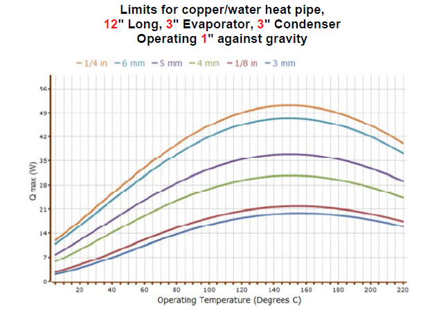

The average practical operating temperature range for water heat pipes is 25-150°C (with an average upper limit of 300°C with a titanium or Monel envelope).
-
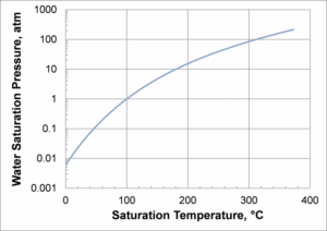
Saturated Water Vapor Pressure as a Function of Temperature
Practically, most water heat pipes are designed to operate above ~25°C). At lower temperatures, the vapor pressure decreases, as well as the vapor density, so the vapor velocity for a given amount of power increases. At temperatures below about 25°C, the viscous and sonic limits become important, limiting the heat pipe power.
- The practical upper-temperature limit for copper/water heat pipes is roughly 150°C, and is set by the maximum allowable stresses in the copper envelope; see Figure 6. At 150°C, the saturated water vapor pressure is 69 psia (477 kPa). Since copper is relatively soft, the required diameter at wall thickness above 150°C C becomes impractical.
Titanium or Monel envelopes increase the maximum operating temperature range for water to 300°C. In this case, the upper-temperature limit is set by the fluid properties. As with any saturated fluid, the saturated vapor and liquid properties become more and more similar as the critical point is approached. A good heat pipe working fluid has a large latent heat and a large surface tension. As shown in the figures below, both the latent heat and the surface tension approach zero near the critical point (373.9°C).
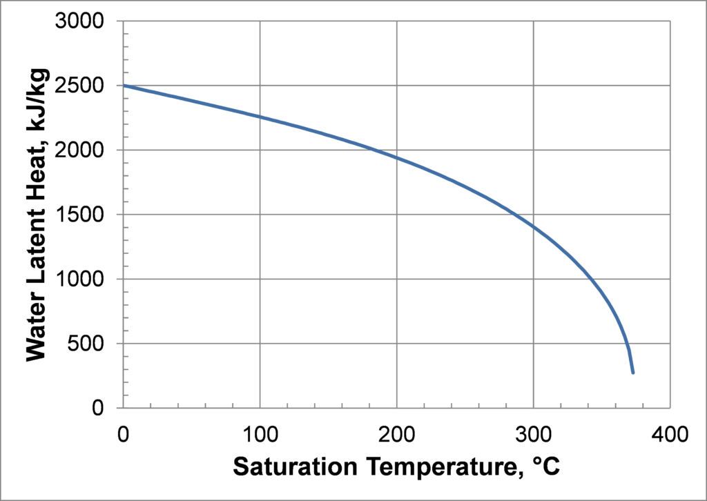
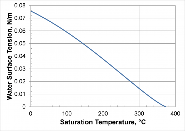
Practical Temperature Limits are discussed in more detail in Compatible Fluids and Materials, where the ‘Working Fluid and Envelope Compatibility Table’ lists practical temperature limits. Note that the upper temperature range for some of these fluids is set by the fact that a superior fluid can be used at higher temperatures.
Heat Pipe Envelope and Fluid Parings
Once the operating temperature is known, the heat pipe designer selects the working fluid. The envelope and wick materials are then selected from materials known to be compatible with the working fluid. If the materials are not compatible, possible incompatibility problems include:
- Copper envelope with water as the working fluid is common for electronics cooling
- Copper or Steel envelopes with Refrigerant R134a fluid is common for Energy Recovery
- Aluminum envelope with Ammonia as the working fluid is common for Spacecraft Thermal Control
- Superalloys: Alkali Metals (Cesium, Potassium, Sodium) for High-Temperature Heat Pipes
- As discussed in Compatible Fluids and Materials there are a large number of other compatible envelope/fluid pairs that are used at other temperature ranges, or when additional factors must be considered. For example, copper/methanol is often used for electronics cooling when the heat pipe needs to operate near or below 0°C, the point at which water freezes. Fluid choices in a given temperature range are ranked by the Merit Number.
Unique Temperature Ranges
High-temperature heat pipes (also known as alkali metal heat pipes) are typically defined as heat pipes that operate between 400 and 1100°C.
Cryogenic heat pipes are specialized, passive, thermal management devices designed to transfer heat efficiently at low temperatures, typically below -150°C (-238°F).
Heat Pipe Performance & Limits
Calculating Transport Capacity
The most important heat pipe design consideration is the amount of power a heat pipe is capable of transferring. Heat pipes can transfer much higher powers for a given temperature gradient than the best metallic conductors. The maximum power that the heat pipe can carry can be set either by the heat source and heat sink conditions or by internal heat pipe limits (can be minimized through proper design).

The temperature drops across a heat pipe are:
- Conduction through the envelope wall and wick
- Evaporation
- Vapor Space Temperature Drop
(usually small compared to the temperature drops required to conduct heat into and out of the heat pipe.) - Condensation
- Conduction through the envelope wick and wall
In addition, there are further temperature drops to bring the heat to the heat pipe evaporator and reject the heat from the condenser, for example, using a finned heat sink and forced convection at the condenser.
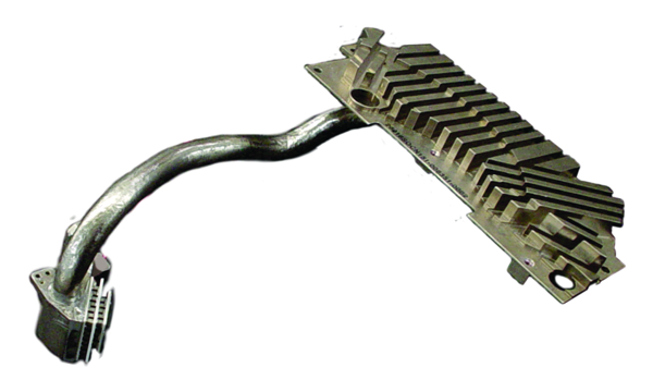
A Heat Pipe Assembly is used to move heat away from the hot side of TEC to an external heat sink.
Critical design point: ensuring that the heat pipes meet your maximum system requirements. If operating conditions cause the heat pipe to exceed its power capacity, the effective conductivity of the heat pipe will be significantly reduced.
Heat Pipe Life Tests
Heat pipes are designed to operate without maintenance for long periods of time, e.g., for more than twenty years in Spacecraft Thermal Control Systems. One requirement is that the envelope, wick, and working fluid must be compatible. Note that compatibility requirements for heat pipes are more stringent than for many other applications. For example, aluminum and water are not compatible, since an aluminum/water heat pipe will generate large amounts of non-condensable gas in hours or days, stopping the heat pipe from operating.
Life tests to determine compatibility have been conducted since heat pipes were rediscovered in the 1960s at the Los Alamos National Labs. In the past, life tests have been conducted on hundreds of different working fluid/envelope/wick combinations, leading to the formation of a long list of compatible envelope/wick/material systems, including copper/water for electronics cooling, and aluminum/ammonia for spacecraft thermal management. Life tests conducted at ACT include Process Control Life Tests, High-Temperature Water Life Tests, and Intermediate Temperature Fluids.
One area of active research on compatibility is the temperature range from 150 to 400°C, see High-Temperature Water Life Tests and Intermediate Temperature Fluids Life Tests section below for more details. ACT has been examining different envelope/fluid pairs in this temperature range for the past decade and has demonstrated several new compatible fluid pairs.

There are a number of different applications that could use heat pipes or loop heat pipes (LHPs) in the intermediate temperature range of 180 to 430ºC (450 to 700 K), including space nuclear power system radiators, fuel cells, geothermal power, waste heat recovery systems, and high-temperature electronics cooling. At temperatures above 400 to 430ºC, alkali metal ( including cesium) heat pipes start to become effective. Below about 430ºC, the vapor density for cesium is so low that the vapor sonic velocity limits the heat transfer. Historically, water was used at temperatures up to about 150ºC. More recently, long-term life tests (as discussed above) have shown that water can be used with titanium or Monel envelopes at temperatures up to 300ºC.
In a past study, researchers had conducted life tests with 30 different intermediate-temperature working fluids, and over 60 different working fluid/envelope combinations. Life tests have been run with three elemental working fluids: sulfur, sulfur-iodine mixtures, and mercury. Other fluids offer benefits over these three liquids in this temperature range. Life tests have been conducted with 19 different organic working fluids. Three sets of organic fluids stand out as good intermediate temperature fluids: (1) Diphenyl, Diphenyl Oxide, and Eutectic Diphenyl/Diphenyl Oxide, (2) Naphthalene, and (3) Toluene.
Another family of potential intermediate temperature fluids are the halides. A halide is a compound of the type MX, where M may be another element or organic compound, and X may be fluorine, chlorine, bromine, iodine, or astatine. Starting with Saaski and Owarski1 (1977), a number of researchers have suggested that halides are potential heat pipe fluids. They are attractive because they are more stable at high temperatures than organic working fluids, and because their Merit numbers peak in the intermediate temperature range.

One reason for conducting heat pipe life tests is to demonstrate the long life of current products. Most Heat Pipe Life Tests (Process Control Life Tests) today are conducted as a Quality Control measure to confirm that the heat pipe fabrication processes are under control. The goal is to demonstrate that ACT’s manufacturing processes result in heat pipe products meeting the most stringent reliability requirements that are typically found in critical mission systems, such as satellites or military-embedded computing equipment.
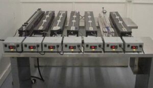
Heat Pipe Life Tests for CCHP Manufacturing Process Control
For example, new aluminum/ammonia Constant Conductance Heat Pipes (CCHPs) are put on life tests whenever a new extrusion is qualified, or the manufacturing process is changed. In the photo to the right, samples of each of ACT’s extrusions for aluminum/ammonia CCHPs are on life test at elevated temperatures to demonstrate the long-term life required in heat pipes for satellites. In this test, the evaporators of these heat pipes are heated with aluminum heater blocks that have internal cartridge heaters. The adiabatic and condenser sections are exposed to the ambient for heat rejection by natural convection. The heat pipes are operated at elevated temperatures, 24 hours a day 365 days a year. Periodically, the life test heat pipes are placed back into performance test fixtures, fully insulated and operated at very low temperatures to look for signs of non-condensable gas (NCG). At these low temperatures, the vapor pressure of ammonia is extremely low and any significant NCG would expand and block part of the condenser section. This would show up as a temperature gradient in the condenser section thermocouples.
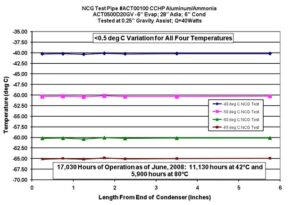
Fig. 1: Heat Pipe Life Tests for Manufacturing Process Control
Figure 1 shows the thermocouple readings along the condenser section of one of the life test heat pipes during an NCG test at -40°C, -50°C, -60°C and -65°C. As of June 2008, the heat pipe showed no sign of NCG after 17,030 hours of operation. Most NCG phenomena occur early in the life of a heat pipe. ACT continues to operate the life test heat pipes at elevated temperatures and periodically performs the NCG test to demonstrate real-time, long-life performance. The results as of April 2014 are shown in Figure 2. The tests are conducted at 80°C, while the highest operating temperature is 40°C. Assuming an Arrhenius relationship, the effective life is doubled for every 10°C above the operating temperature, or 16 times.
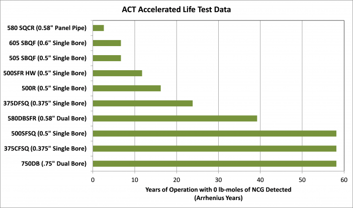

Copper is the traditional envelope and wick material for water at temperatures below about 150°C, with a large experience base. At higher temperatures, where the vapor pressure of water increases rapidly, copper is not acceptable for the envelope material, due to its relatively high mass and low strength. Titanium, titanium alloys, Monel 400, and Monel K500 have higher yield strength and lower density than copper. Over the past 20 years, ACT has conducted life tests to verify that these materials are compatible with water, hence can be used in thinner and lighter-weight heat pipes than copper at a given operating temperature and working fluid vapor pressure. The materials under test include:
- Ti CP-2 Heat Pipe, with CP (Commercially Pure) Titanium Screen
- Monel K500 Heat Pipe, with Monel 400 Screen
- Ti Grade 5 Cylinder (6% Aluminum, 4% Vanadium), with CP Titanium Screen
- Ti Grade 7 Cylinder (0.2% Pd), with CP Titanium Screen
- Ti CP-2 Cylinder, with 21S foil and CP Titanium Screen (21S tubing was not available)
- Ti Grade 9 cylinder (3% Aluminum, 2.5% Vanadium) with CP Titanium Screen
- Ti CP-2 Heat Pipe, with Sintered Cylindrical Wick
- Ti CP-2 Heat Pipe, with Integral Grooves
- Monel 400 Heat Pipe, with Monel 400 Screen
- Monel K500 Heat Pipe, with sintered Monel 400 wick
- Monel 400 Heat Pipe, with sintered Monel 400 wick
The table below shows the different life test pipes on test at ACT. Monel 400 is a solid solution alloy with roughly 63% nickel and 30% copper. It is a single-phase alloy since copper and nickel are mutually soluble in all proportions. It can only be hardened by cold working. Monel K500 is a similar nickel-copper alloy, with the addition of small amounts of aluminum and titanium that give greater strength and hardness. The system is age-hardened by heating so that small particles of Ni3(Ti, Al) are precipitated throughout the matrix, increasing the strength of the material. The advantage of Monel K-500 is that the strength can be partially recovered after a wick is sintered inside.
|
Initial Qty. |
Wall Material |
Wick |
Operating Temperature |
Operating Hours |
|---|---|---|---|---|
|
4 |
Monel K 500 |
200×200 Monel 400 Screen : 0.064 mm wire |
550 & 500 K |
72,192 hours |
|
4 |
CP-2 Ti |
150x150CP-Ti Screen : 0.069 mm wire |
550 & 500 K |
72,192 hours |
|
2 |
CP-2 Ti |
Sintered Titanium : -35+60 Mesh CP-2 |
550 K |
60,672 hours |
|
2 |
CP-2 Ti |
100 x100 CP-Ti Screen : 0.05 mm wire |
550 K |
61,064 hours |
|
1 |
CP-2 Ti |
Integral Grooves |
550 K |
41,345 hours |
|
2 |
CP-2 Ti |
100 x100 CP-Ti Screen : 0.05 mm wire |
550 K |
62,622 hours |
|
2 |
Grade 5 Ti |
100 x100 CP-Ti Screen : 0.05 mm wire |
550 K |
69,845 hours |
|
2 |
Grade 7 Ti |
100 x100 CP-Ti Screen : 0.05 mm wire |
550 K |
60,672 hours |
|
2 |
Grade 9 Ti |
100 x100 CP-Ti Screen : 0.05 mm wire |
550 K |
60,072 hours |
|
2 |
Monel 400 |
120×120 Monel 400 Screen : 0.05 mm wire |
550K |
60,168 hours |
|
2 |
Monel K 500 |
120×120 Monel 400 Screen : 0.05 mm wire |
550K |
67,536 hours |
|
2 |
Monel 400 |
-100+170 Mesh Monel 400 Powder |
550K |
58,824 hours |
|
2 |
Monel K 500 |
-100+170 Mesh Monel 400 Powder |
550K |
57,792 hours |
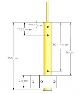
Figure 3, above, shows a schematic of a typical life test heat pipe set up in a heater block. The life tests are gravity aided, and cooled by natural convection. The life test pipes are instrumented with three thermocouples. One thermocouple is located just above the heater block, while the other two are located in the heat pipe condenser. During operation, the temperature difference between the evaporator and condenser are monitored to detect non-condensable gas (NCG). Any NCG is swept by the working fluid to the end of the condenser, where it forms a cold end.
Figure 4, below, shows the titanium/water and Monel/water heat pipes set up in the heater blocks, prior to testing. One thermocouple is located just above the heater block, the other two are located in the heat pipe condenser (all of the thermocouples are under the hose clamps) in Figure 4.
LESSONS LEARNED FROM A SERIES OF HALIDE LIFE TESTS – Read the case study
Heat Pipe Limits
There are five primary heat pipe transport limitations that must be considered during design: viscous, sonic, capillary, entrainment/flooding and boiling; see table below. These limits are a function of many variables including operating temperature, wick selection, and fluid properties. The most common limit for terrestrial applications is the capillary limit. ACT developed a heat pipe calculator for terrestrial copper-water heat pipes to help customers design accordingly.
Heat Pipe and Thermosyphon Limits Table
| Heat Pipe Limit | Description | Cause |
| Viscous (Vapor Pressure) | Viscous forces prevent vapor flow within the heat pipe. | Heat pipe operating near triple point with a very low vapor pressure – need to use a different working fluid. |
| Sonic | Vapor flow reaches sonic velocity when leaving the evaporator, choking the flow. | Too much power at lower operating temperature. Typically this is seen at start-up and will self-correct. |
| Heat Pipe Entrainment | The power input is too high. Wick structure not designed appropriately for power and orientation. | Not enough vapor space for the given power requirement. Occurs at low temperatures. |
| Thermosyphon Flooding | The power input is too high. Wick structure is not designed appropriately for power and orientation. | Not enough vapor space for the given power requirement. Occurs at low temperatures. |
| Capillary | The capillary action of the wick structure cannot overcome gravitational, liquid, and vapor flow pressure drops. | High-velocity vapor flow prevents liquid return in a gravity-aided thermosyphon. |
| Boiling | Boiling occurs in the wick which prevents liquid return | High radial heat flux into the heat pipe evaporator. |
VISCOUS (VAPOR PRESSURE)
Sonic
Note: as the vapor temperature in the heat pipe is lowered, the vapor pressure drops. To carry a given amount of heat, the vapor velocity must increase, which in turn increases the pressure drop from the evaporator to the condenser. At these low vapor pressures, compressible flow effects become important.
Design rule of thumb, always operate with powers less than one-half of the sonic limit.
The sonic limit is reached when the Mach number reaches 1 at the beginning of the heat pipe adiabatic section. There are a number of ways to reach the sonic limit in compressible flow, such as decreasing the flow area, adding heat, and frictional effects.
Sonic Limit Calculation
The heat pipe sonic limit is approached by mass addition, where mass is added to the flow rate from the start to the end of the heat pipe evaporator:

- where:
mDot_Sonic Mass flow at the entrance to the adiabatic section, when the flow is choked, kg/s
ρV Vapor density, kg/m3
VSound_V Speed of sound in the vapor, m/s
AVapor Heat pipe vapor space area, measured perpendicular to the flow, m2
γ Ratio of specific heats, cp/cv

The sonic limit is then:
- where:
qSonic Sonic limit, W
λfg Latent heat, liquid to vapor, J/kg
Sonic Limit Example
The chart below compares heat pipe power versus temperature for identical heat pipes using either cesium or potassium as the working fluid. The sonic and capillary limits were calculated, and then curves using the lower of the two limits were plotted in the figure.
On the left side of the graph, the maximum heat pipe power is set by the sonic limit (the roughly parabolic part of the curve), while on the right side of the graph, the maximum power is set by the capillary limit (the roughly flat part of the curve).
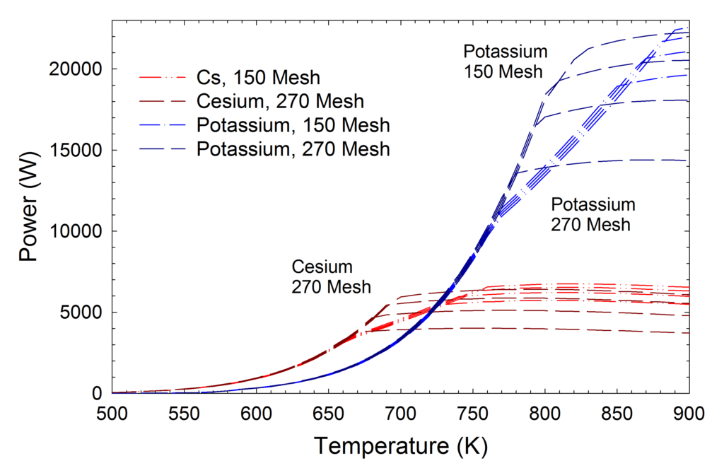
At lower temperatures, more power can be carried with cesium, since it has a higher vapor density (and higher sonic limit) at any given temperature. Once the temperature is increased above roughly 500°C, the potassium heat pipe carries more power (for this particular design). This is the reason that cesium is normally used at temperatures below 600°C, and is replaced by potassium and then sodium at higher temperatures.
Heat Pipe Entrainment/Thermosyphon Flooding
Like the viscous and sonic limits, the entrainment or flooding limit is related to the vapor velocity and is more significant at lower temperatures. The reason is that the vapor pressure and vapor density decrease as the temperature is lowered, so the vapor velocity must increase to carry the same power.
Design rule of thumb, always operate with powers less than 0.75 of the entrainment or flooding limit.
Heat Pipe Entrainment
In a heat pipe, the vapor flows from the evaporator to the condenser, with countercurrent liquid flow from the condenser to the evaporator. The entrainment limit is reached when the vapor velocity in the heat pipe is high enough to shear liquid from the wick.
The entrainment limit is given by:

- where:
qEntrain Entrainment limit, W
AVapor Heat pipe vapor space area, measured perpendicular to the flow, m2
λfg Latent heat, liquid to vapor, J/kg
σ Surface tension, N/m
ρV Vapor density, kg/m3
rc Wick pore radius, m
Thermosyphon Flooding Limit
In a thermosyphon, the vapor flows from the evaporator at the bottom of the thermosyphon to the condenser at the top of the thermosyphon. At the same time, the condensed liquid drains back to the evaporator along the wall (driven by gravity). The flooding limit is reached when the vapor velocity in the thermosyphon is high enough that shear stresses prevent liquid from returning to the evaporator.
- Note: loop thermosyphons are sometimes used to eliminate the flooding limit since the vapor and liquid flows are separated from each other.
One flooding correlation that is often used was developed by A. Faghri and published in the book, Heat Pipe Science and Technology, CRC Press, pp. 387-397, 1995.
The first step is to define the Bond number, a dimensional number that measures the importance of surface tension forces versus body forces:

- Where:
ID Internal Diameter, m
ρL Liquid density, kg/m3
ρV Vapor density, kg/m3
g gravity or acceleration, m/s2
σ Surface tension, N/m
The flooding constant, KFlooding, is defined as:


Capillary
During heat pipe operation the working fluid evaporates in the evaporator and condenses in the condenser, transferring the latent heat from one end of the heat pipe to the other. The liquid condensate is passively returned to the evaporator by capillary forces in the wick.
Design rule of thumb: the capillary limit states that the capillary force generated by the wick must be larger than the sum of the pressure drops in the wick.
Capillary Limit Calculation
The maximum power that the heat pipe can carry and still return the condensate by capillary forces is the capillary limit:
- where:
ΔPc Capillary force generated in the wick, Pa
ΔPg Pressure drop due to gravitation and acceleration, Pa
ΔPL Liquid pressure drop in the wick, Pa
ΔPV Vapor pressure drop in the heat pipe, Pa
ΔPC, Capillary Force
The capillary pumping capability depends on surface tension and two radii of curvature of the liquid/vapor interface, measured perpendicular to each other:

where:
σ Surface tension, N/m Radii of Curvaturer 1 and r2, are the radii of curvature (m)
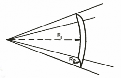
For sintered and screen wicks, the two radii are identical, so the equation reduces to:

- where:
rc is the pore radius
One of the radii is infinite for grooves, so the equation becomes:

ΔPG, Gravitational Pressure Drop The gravitational pressure drop is:

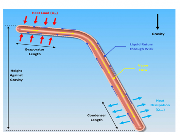
- where: The adverse elevation, h, is the height of the evaporator over the condenser.
ρL Liquid density, kg/m3
ρV Vapor density, kg/m3
g gravity or acceleration, m/s2
h adverse heat pipe elevation, m; See Figure 4.
Since the vapor density is typically much less than the liquid density, this reduces to:

PL AND ΔPV, Liquid and Vapor Pressure Drops
The mass flow rate circulating through the heat pipe is directly proportional to the power:
- where:

| QHeatPipe | heat pipe power, W |
| mDot | liquid mass flow, kg/s |
| λ | latent heat, J/kg |
With the exception of grooved wicks, the liquid pressure drop in the wick, ΔPL, is calculated with Darcy’s law for fluid flow through a porous media:
- where:

| μL | Liquid viscosity, kg/(m s) |
| k | Wick permeability, an intrinsic property of the wick, m2 |
| AWick | Wick area, measured perpendicular to the liquid flow direction, m2 |
| LEffective | Effective length of the heat pipe, defined below, m |
Solving for ΔPL, the equation becomes:

For a grooved wick, ΔPL is calculated with the standard pressure drop equations, found in any fluid mechanics textbook. Similarly, ΔPV for all heat pipes is calculated using the standard pressure drop equations.
Effective Length
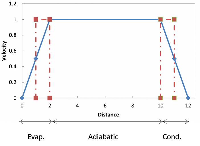
As discussed above, the capillary limit is calculated using simple, one-dimensional equations. An effective length is used in the pressure drop equations to account for the variation in velocities along the heat pipe.
As shown in the figure at the right, the full velocity and half of the evaporator and condenser length are used for the effective length, to compensate for the changing velocity. The vapor and liquid velocities at the start of the evaporator are zero. They increase linearly due to evaporation to a maximum at the start of the adiabatic section and then are constant in the adiabatic section. In the condenser, condensation causes the vapor and liquid velocities to decrease linearly to zero at the end of the condenser.

To account for the varying velocity, an effective length is used to calculate the vapor and liquid pressure drops.
Capillary Limit Example
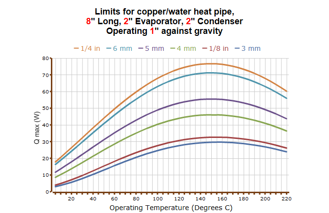
The calculation shown in the chart to the right shows typical capillary limits as a function of temperature for several different heat pipe diameters, calculated using ACT’s heat pipe calculator. The heat pipe limit generally peaks somewhere in the middle of the working fluid temperature range: At low temperatures, the capillary limit is restricted by high liquid viscosity and low vapor pressure (low vapor density → high vapor velocities). At high temperatures (approaching the critical point), the maximum power drops off, since the surface tension and latent heat of vaporization go to zero.
Boiling
When a low heat flux is applied to a heat pipe evaporator, the heat is conducted through the wick, and liquid vaporizes on the inner surface of the wick, into the vapor chamber. As the heat flux increases, the temperature difference across the wick increases linearly. The boiling limit or heat flux limit takes place when the transverse heat flux into the evaporator is enough to create nucleate boiling in the wick of the evaporator section. This generates vapor bubbles, which can become trapped in the wick, blocking the liquid from coming back, which can result in evaporator wick dry-out.
Boiling Limit Calculation
The boiling limit can be calculated by applying the nucleate boiling theory:

where:
| QBoil | Boiling limit, W |
| LEvap | Evaporator length, m |
| keff | Effective thermal conductivity of the liquid-wick combination, W/(m K) |
| T | Vapor temperature, K |
| λ | Latent heat of vaporization, J/kg |
| ρVapor | Vapor density, kg/m3 |
| rIDWall | Inner radius of the heat pipe wall, m |
| rODVapor | Radius of the vapor core, m |
| σ | Surface tension, N/m |
| PCapillary | Capillary pressure of the wick structure, Pa |
| rnucleate | Nucleation site radius, which can be [2.54 x 10⁻⁵ m to 2.54 x 10⁻⁷ m] for conventional heat pipes |
Experimental Boiling Limits
- Rules of thumb for the boiling limit in some typical heat pipe wicks:
- Sintered Wicks with Water: ~ 75 W/cm2
- Screen Wicks with Water: ~ 75 Wcm2
- Grooved, Aluminum Wicks with Ammonia: ~ 15 W/cm2
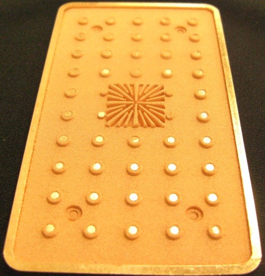
- In special cases, wicks can be designed with much higher boiling limits. The photo at the right shows a specially designed copper/water vapor chamber wick, which can remove 750 W/cm2 over a 1 cm2 area, shown in the center of the figure.
Heat Pipe Performance Limit
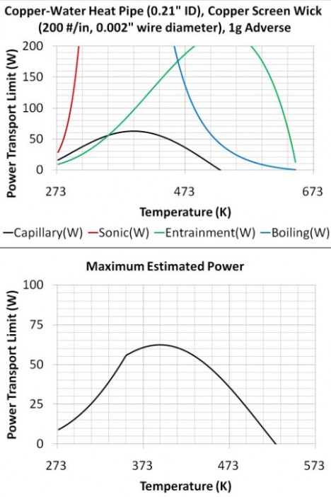
To calculate the heat pipe performance limit, the different heat pipe limits are plotted as a function of temperature; see Top Graph at right that shows that the entrainment and capillary limits are controlled over specific temperature ranges.
- Note: the viscous limit is not shown, since it is not relevant in the normal operating temperature range.
The lowest limit at each temperature is then the heat pipe performance limit curve, which is calculated by taking the lowest limit at each temp.; see bottom graph at right.
The viscous, sonic, and entrainment/flooding limits are all related to the vapor velocity and are more significant at lower temperatures. The reason is that the vapor pressure and vapor density decrease as the temperature is lowered, so the vapor velocity must increase to carry the same power.
Water Heat Pipe Parameters and Limitations
Heat Pipes are passive two-phase heat transfer devices that transfer heat by evaporation and condensation. The heat pipes used in electronics thermal management, Spot Cooling Heat Pipes, HiK™ Plates., and Vapor Chambers, all typically use water as the working fluid.
- Note: This section pertains specifically to water heat pipes; heat pipes with other working fluids have different limitations, one reason being that their operating temperature ranges are different.
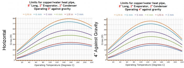
Maximum power for a given heat pipe geometry drops off at high and low temperatures and as the adverse elevation increases.
There are three general limitations for passive two-phase devices, which include heat pipes, HiK™ plates, and vapor chambers:
- Temperature
- Vertical Height
- Acceleration
Operating Temperature
All heat pipes have a temperature range over which they have the best performance. Maximum power versus operating temperature for typical water heat pipes is shown in the Copper Water Heat Pipe Calculation output above. The maximum power is high from roughly 60 to 200°C, falling off gradually at lower temperatures (the power also falls off at higher temperatures, but this is typically not a concern for electronics cooling).
The drop-off in power as the temperature is reduced is set by the fluid properties of the working fluid. As the temperature (and associated saturation pressure) of the water is reduced, the water vapor density is also reduced. To carry a given amount of power, the vapor velocity in the heat pipe must increase, which in turn increases the pressure drop in the heat pipe while reducing the power that can be carried.
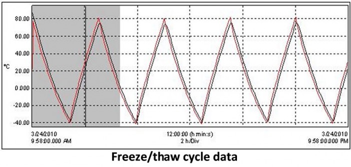
ACT generally designs heat pipes to operate at temperatures above ~25°C. At temperatures below 0°C, the water is frozen in the heat pipe, and conduction through the heat pipe wall is the primary method of heat removal. It is important to note that this is not generally a problem for electronics cooling, since the primary concern is to maintain the electronics below a maximum temperature. When the system starts up from a colder condition, say -40°C, the electronics will warm up until the temperature is around 25°C, and the heat pipe starts operating. Properly designed heat pipes can operate after thousands of freeze/thaw cycles, see testing data graphed at right.
If operation below 25°C is required, then the thermal designer can switch to a different working fluid such as methanol, or use an encapsulated conduction card.
Adverse Vertical Height
Heat pipes return liquid from the condenser to the evaporator through a wick, which allows them to operate in any orientation. During operation, capillary forces in the wick must overcome the sum of liquid and vapor pressure drops as well as the adverse gravity head and acceleration. As the adverse elevation is increased (evaporator located above condenser), more of the wick pumping capability is used to counteract the adverse gravity head, and the maximum heat pipe power is reduced. This can be seen when comparing the Copper Water Heat Pipe Calculation output from above, sides (a) and (b), which show power with a level heat pipe, and a heat pipe with an adverse 4-inch (10 cm) elevation, respectively. It can be seen that the maximum power is reduced significantly. Other adverse elevations can be examined through calculations with ACT’s heat pipe calculator.
In general, water heat pipes can operate with the evaporator elevated a maximum of 9-10 inches (23-25 cm) above the condenser. This sets the maximum elevation for spot-cooling heat pipes and vapor chambers. This elevation is doubled for HiK™ plates to 18-20 inches (46-50 cm), when the HiK™ plates are cooled on both the top and the bottom, and a double set of heat pipes is embedded. Note that if the electronics and sink can be arranged so that the electronics are lower than the heat sink, then the heat pipe behaves as a thermosyphon. In this orientation, gravity returns the liquid to the evaporator rather than capillary forces, and the heat pipe length is essentially unlimited.
Acceleration
During operation, capillary forces in the wick must overcome the sum of liquid and vapor pressure drops as well as the adverse gravity head and acceleration. Water heat pipes will stop operating under high adverse acceleration when the wick can no longer return condensate to the evaporator, and the heat pipe de-primes, or dries out. The wick will quickly re-prime after the acceleration stops. Heat is stored by a rise in temperature during acceleration. Most accelerations are relatively short, and this temperature rise is acceptable.
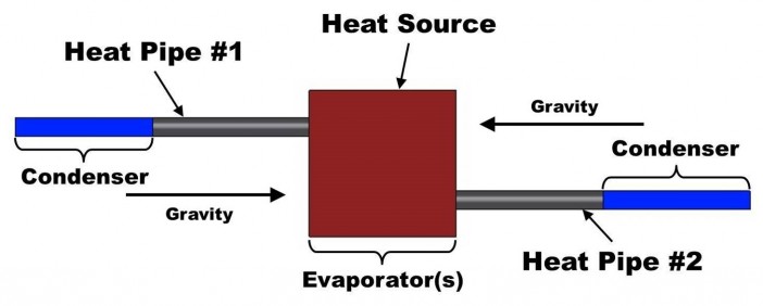
If the acceleration is of longer duration, then the thermal designer has three choices:
- Design the heat pipes “gravity aided” under acceleration if the axis and direction of the acceleration are known.
- Arrange heat pipes in pairs, so that one pipe is always “gravity aided”; see image at right.
- Use an encapsulated conduction card.
Different Types of Heat Pipes

- How do They Work?
- Heat Pipe Fluids
- Heat Pipe Envelope and Fluid Parings
- Unique Temperature Ranges
- Heat Pipe Performance & Limits
- Heat Pipe Life Tests
- VISCOUS (VAPOR PRESSURE)
- Heat Pipe Entrainment/Thermosyphon Flooding
- Capillary
- Boiling
- Experimental Boiling Limits
- Water Heat Pipe Parameters and Limitations
- Different Types of Heat Pipes

