ACT Logo
|ADVANCED COOLING TECHNOLOGIES
0
Cart Icon
Contact Us
  • Thermal Solutions
    • Passive Thermal Solutions
      • Heat Pipes
        • HiK Plates­™/ Heat Pipe Assemblies
        • Pulsating Heat Pipes
        • Vapor Chambers
        • High Temperature Heat Pipes
      • Loop Thermosyphon
      • Phase Change Based Solutions
        • PCM Heat Sinks
      • Liquid Cold Plates
    • Enclosure Cooling Products
      • HSC (Heat Sink Coolers)
      • HPC (Heat Pipe Coolers)
      • TEC (Thermoelectric Coolers)
      • VCC (Vapor Compression Coolers)
      • Enclosure Cooling Selection Tool
    • Space Thermal Control
      • Constant Conductance Heat Pipes
      • Variable Conductance Heat Pipes
      • Space Copper-Water Heat Pipes
      • Loop Heat Pipes
      • Space VPX
      • Liquid Cooling
    • Active Thermal Management Solutions
      • Liquid Cooling
      • Pumped Two-Phase
      • Liquid-Air HX
      • Tekgard® ECUs
      • Vaphtek™ ECU
      • Tekgard® Chillers
    • Embedded Computing Solutions
      • ICE-Lok®
      • VME/ VPX Card Frames
      • Conduction Cooled Chassis
      • Liquid Cooled Chassis
    • HVAC Energy Recovery
      • AAHX
      • WAHX
  • Engineering Services
    • Research & Development
      • Our Research & Development Team
      • Emerging Technology
      • Technical Papers
      • Other Research Interests
    • Product Development
    • Space Thermal & Structural Analysis
    • Manufacturing
    • Lifecycle Management
  • Industries
    • Energy
      • Wind Energy
      • Nuclear Energy
      • Power Conversion
      • Energy Storage
      • HVAC Energy Recovery
    • Space
    • HVAC Energy Recovery
    • Defense
    • Medical
    • Data Centers
    • Other
  • Resources
    • Blog
    • Calculators & Selection Tools
      • AAHX Selection Tool
      • Enclosure Cooling Selection Tool
      • Heat Pipe Calculator
      • PCM Calculator
      • WAHX Selection Tool
    • Publications
      • Published Articles
      • Patents
      • Technical Papers
    • Learning Center
      • Heat Pipe Learning Center
      • Pumped Two-Phase Learning Center
      • PCM Learning Center
      • HVAC Learning Center
      • Videos
      • eBooks
      • Brochures
      • Case Studies
      • Webinars
    • Find your Rep
  • Shop
    • Sealed Enclosure Coolers
    • Heat Pipe Coolers
      • Heat Pipe Cooler Accessories
    • Heat Sink Coolers
      • Heat Sink Cooler Accessories
    • Thermoelectric Coolers
    • Vapor Compression Coolers
  • About
    • Careers
    • Events
    • News
    • Sustainability
    • ACT Leadership
  • Contact
0
Cart Icon View Cart

Environmental Control Unit Redundancy: Asking the Important Questions

Military service members rely on Environmental Control Units (ECUs) for a variety of daily applications, including such life-sustaining services as shelter support and weapon-defense systems. But what happens when an ECU goes down? What measures can be taken to ensure the safety of warfighters and the operability of military equipment? This is where ECU redundancy becomes a vital aspect of system design. Having two ECUs in support of a particular application can maintain operability in the event of a unit failure, and—in the most extreme cases—it can be the difference between life and death. Suffice to say, it is important to evaluate the necessity of a redundant system, and Advanced Cooling Technologies (ACT) engineers are available to help customers through this critical step of the design phase.

Of course, the addition of another ECU results in further costs, so it is not an ideal solution for every application. In determining whether or not a redundant ECU system is a good fit, ACT engineers ask customers to consider three key questions:

What type of environment will the system encounter?

As the military operates around the globe, the environmental conditions that a system will face can vary drastically. A sea-bound system could face salt spray and the frigid temperatures of the Arctic, while a land-based system could see the sweltering triple-digit temperatures of the sandy deserts. Understanding where an ECU will be deployed can help ACT engineers determine whether or not a redundant system is advisable; the tougher the conditions, the more a customer may want to consider this additional unit as a safety precaution. Likewise, ACT engineers can prepare the ECUs for the elements that await them by including environment-specific additions, such as corrosion-resistant coatings. This ensures the longest life and highest performance out of an ECU system.

Will this unit be deployed in a remote location?

Remote location radar dome

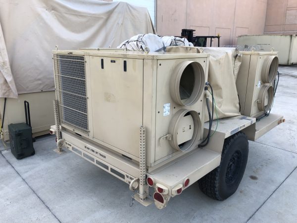
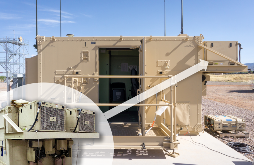
When ECUs are deployed in remote or unoccupied areas, it can be harder to get them back to working order should they experience some form of failure. Tools, parts, and service technicians are scarce in these environments, and it is likely that a malfunctioning system will be down for a prolonged time if there is only one ECU supporting it. A redundant ECU system ensures that, if the operating unit goes down, the second ECU turns on to continue operation. Common examples of remote applications that benefit from a redundant system include control rooms, mobile data centers, and radar domes.

What are the consequences?

Most importantly, in the event that a single-ECU system goes down, what will happen to the equipment or personnel that are supported by it? Are lives at stake? If the answer is yes, it is best to assume that a single-ECU system is a no-ECU system; warfighters cannot take a chance that their life-sustaining ECU will experience a failure in the field without a backup. A redundant system can keep operations running smoothly in what could otherwise be dire circumstances. Additionally, redundant systems can share the same replacement parts kits between each of the units, making it easier to repair the down ECU while the second unit continues to run.

Redundant Environmental Control Unit Options

Should ACT engineers determine a redundant ECU setup is advisable, there are several options to consider:

I. Lead/Lag

Lead/Lag ECUs

ACT’s typical redundant setup, the lead/lag (or primary/backup) method features two ECUs that function as one system; only one ECU can be operated at a time (usually due to power constraints). The first ECU will operate in an automatic mode (vent/heat/cool) for a finite period of time without a fault present (typically 168 hours or one week, which can be programmed into the system components). At this point, the ECU will de-energize, and the second ECU will energize and follow the same pattern. This keeps equal wear-and-tear on the ECUs and ensures both are functional. If a fault were to occur, the operating ECU will turn off, and the backup ECU will automatically energize. This is a critical feature for continuing to keep the customer’s equipment cool/warm enough to operate while also communicating to the customer that a fault has occurred. This is ideal for unmanned systems where the cooling system needs to react autonomously to a unit failure.

II. Dual- ECU

Dual-ECU setups have two ECUs that perform as one. This configuration may be the result of size constraints where a hypothetical ECU that would be big enough to handle the workload simply cannot fit in the space in which it needs to operate. Instead, the load is shared by two smaller ECUs that do fit. This setup is appropriate when reduced capacity during an ECU failure is acceptable.

III. Combination Setups

ACT also manufactures solutions that have the capability to switch between running one ECU at a time to running both units simultaneously. This configuration may be necessary when there is a possible excess of heat. For example, a requirement could call for the output of 50,000 BTU/hr for a finite period of time when a typical load is just 40,000 BTU/hr. The lead ECU will cool/heat until an amount of time above/below the thermostat setpoint has passed, at which point the backup ECU will also energize. Both ECUs will run until the load is below the threshold where only one ECU is needed to maintain the space temperature.

There is certainly a lot to consider when designing an ECU system, and the possibility of redundancy can be a complicated topic to explore. ACT engineers are available to help customers find the best solution for their particular operations.

Learn more about ACT’s Tekgard® Brand of ECUs

Contact ACT to discuss your project

Top Up facing arrow in a square
Page Index
  1. What type of environment will the system encounter?
    1. Will this unit be deployed in a remote location?
    2. What are the consequences?
  2. Redundant Environmental Control Unit Options
Related Resources
Lifecycle Management Icon for Lifecycle Management Tekgard® ECUs Icon for Tekgard® ECUs
ACT Logo
Advanced Cooling Technologies, Inc.
1046 New Holland Avenue
Lancaster, Pennsylvania 17601, USA
(717) 295-6061 Contact Our Experts
linkedin youtube twitter facebook
  • shop products online
  • sitemap
  • privacy policy
  • terms & conditions
  • ISO9001 & AS9100 CERTIFIED, ITAR REGISTERED

Copyright 2025. All rights reserved.