Liquid cooling is a time-proven approach to maintaining safe operating temperatures of high heat flux electronics. It’s effective, capable of rejecting high heat loads and well understood. Although liquid cooled approaches are active, meaning they consume power and have mechanical components, they are often the best solution when power and temperature requirements demand it. In some cases, the liquid cooling lines need to be routed close to the heat-generating components to maintain thermal goals. This can, however, present a significant risk to the system in the event of a leak. If there were to be a fluid leak in the system, it would result in catastrophic failure to the electronics system.
Risk Mitigation to mitigate fluid leaks
One way to mitigate the fluid leak scenario is by decoupling the ultimate heat sink (liquid) from the heat-generating devices. By adding heat pipes to transfer heat at low thermal resistance, you can increase reliability with a minimal performance impact. The added distance between electronics and coolant could lead to a thermal penalty.
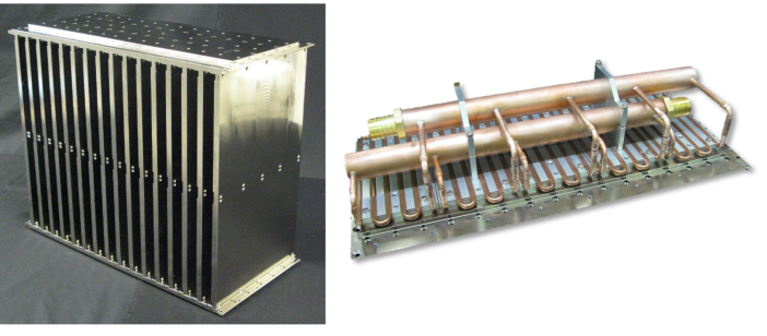
In the example below, ACT designed, developed, and tested a thermal solution that is capable of transferring heat from within an electronics chassis to an external liquid cooling loop. This included the heat pipe heat spreader design as well as the series/parallel flow channel liquid cold plate that acted as the ultimate heat sink. The electronics assembly, referred as a slat, has a fixed thermal resistance that is set by the customer’s electronics design. This slat is mounted to a heat pipe embedded, or HiK™ heat spreader, which transfers the heat through a series of interfaces and aluminum conduction paths to the external liquid cold plates which are mounted on the top and bottom of the electronics chassis.
Each HiK™ heat spreader in this assembly transfers 180W. The power is split between the two cooling loops with each handing 90W of power. This is important to note since heat pipes work both gravity assisted, and against gravity. Since the heat pipes were designed to work in both of orientations, and have a fixed thermal resistance, the electronics were able to maintain symmetric thermal gradients using both the upper and lower HiK™ heat spreaders. There is a combination of 16 HiK™ plates within this system for a total heat load of 2,880W.
Customer Collaboration- What does the design process look like?
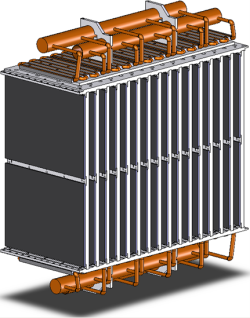
ACT began the effort with a detailed thermal analysis that mapped the thermal resistance network from the heat-generating components to the chilled water supply. Several design iterations were required to determine a cold plate design that met both temperature uniformity and pressure drop goals. The final solution was a serpentine tube-in-plate design to ultimately meet necessary thermal requirements. Each serpentine removed heat from four of the HiK™ plates, four serpentines were used in parallel to reject heat from the 16 HiK™ plates within the system as seen in the Figure 1 CAD drawing below.

Manufacturing
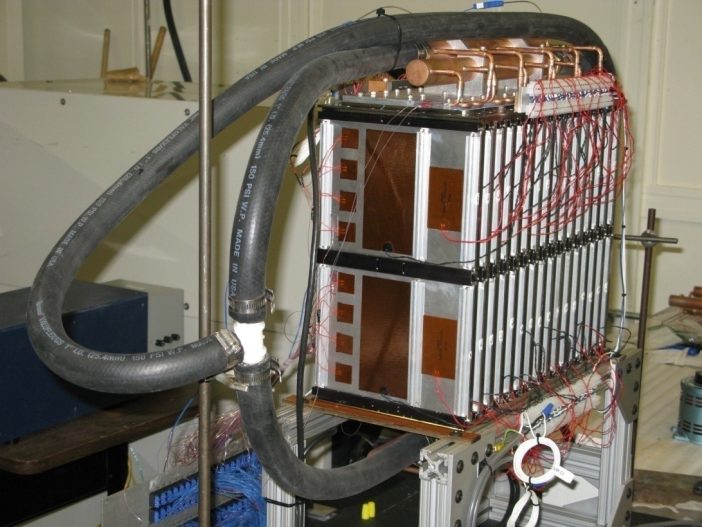
Following the thermal analysis of the proposed system and the customers’ approval, the ACT team was ready to move forward with manufacturing the prototype. The first step in production was manufacturing the heat pipes, aluminum components and the manifold assembly. Commercial off-the-shelf cold plates were used in lieu of an all-aluminum assembly in order to simplify and expedite the prototype lead time. Following assembly of the prototype, heat loads were simulated using film heaters that matched the heat input footprint provided by the customer and chilled water was supplied using a commercial chiller. An image of the test setup is shown in Figure 2.

Testing
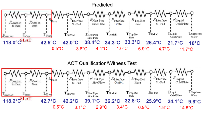
Results of the testing in comparison to the thermal predictions are shown in Figure 3. The max junction temperature was predicted to be 118.0°C whereas the assembly measured 118.2°C. The temperature drop highlighted in the red boxes on the left of Figure 3 represents the junction-to-case temperature drop within the electronics slot. This information was provided by the customer and is fixed in the comparison. There are minor differences between the predicted and measured interface materials. The predicted temperature drop of the cold plate was 11.7°C and measured a 14.5°C. One key temperature drop to highlight is for the HiK™ plate. The prediction estimated a 4.1°C temperature drop, whereas the assembly measured only 2.9°C.

Summary
It’s not uncommon for large chassis to have such high waste heat that it requires liquid cooling. While this is less reliable than conduction or air-cooled solution, there are methods to increase reliability by separating the liquid flow and potential leak points from the high-value electronics. By using heat pipes to transfer the heat from the source to the liquid-cooled sink, you can vastly reduce thermal resistance in this conduction path and keep the liquid loop a safe distance from the electronics. This hybrid approach can provide both high thermal performance and high reliability when compared to alternative solutions.

