

A Heat Pipe Loop (HPL) is a completely passive heat transfer device that has features found in both heat pipes and loop heat pipes. This technology was invented by ACT.
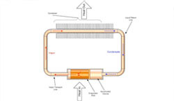
Figure 1 Heat Pipe Loop Schematic
OPERATING PRINCIPLES OF A HEAT PIPE LOOP
Figure 1 (right) is a schematic diagram illustrating the operating principles of one version of the Heat Pipe Loop design. The evaporator is like a heat pipe evaporator, with a wick lining the inner wall. The liquid is evaporated off the wick surface by the heat input. The vapor flows through the vapor transport line toward the condenser. In the condenser, the vapor is condensed and the condensed liquid is slightly subcooled before exiting the condenser. The subcooled liquid flows through the liquid transport line toward the reservoir (or accumulator) adjacent to the evaporator. The liquid subcooling requirement is similar to the loop heat pipe operation in that the heat leak from the evaporator to the reservoir must be compensated by the subcooled liquid entering the reservoir to maintain a steady-state operation. The evaporator wick draws the liquid from the reservoir to complete the fluid circulation inside the heat pipe loop.
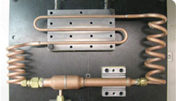
Figure 2 Prototype Heat Pipe Loop
Like in a loop heat pipe, the Heat Pipe Loop is made self-priming by carefully controlling the volumes of the reservoir, condenser and vapor and liquid lines so that liquid is always available to the evaporator wick. The reservoir volume and fluid charge are set to ensure there is always fluid in the reservoir, even if the condenser and vapor and liquid lines are fully filled.
HOW ARE LOOP HEAT PIPES (LHPS) DIFFERENT FROM HEAT PIPE LOOPS (HPL)?
Compared to loop heat pipes, the Heat Pipe Loop’s heat pipe-like evaporator design enables it to be inherently inexpensive to manufacture and capable of handling high heat flux input. Compared to heat pipes, the Heat Pipe Loop can transport much more heat over longer distances, possibly through flexible transport lines. This is particularly useful for commercial and military electronics cooling applications where the heat source (electronic devices) and the heat sink (usually located at the circuit card edge or chassis) are often located apart.
Figure 2 is a photo of a prototype Heat Pipe Loop that was made of copper tubing and used water as the working fluid. The liquid and vapor transport lines are made into coils to simulate the long distances between the evaporator and condenser. This Heat Pipe Loop was designed to operate in the temperature range of 40 to 150°C and transfer more than 250W of heat from the evaporator to the condenser.
Figure 3 Prototype Heat Pipe Loop Test Results
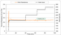
Figure 4 Prototype Heat Pipe Loop Evaporator
Thermal Resistances (click for larger version)
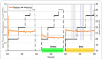
Figure 5 Prototype Heat Pipe Loop Performance at Vibration and Shock Conditions
Figure 3 shows one test sequence where the prototype Heat Pipe Loop was subject to incrementally increasing heat input to the evaporator. The condenser heat sink temperature was maintained between 45 and 47ºC during the test sequence. As seen, the Heat Pipe Loop reached a steady state (without any sign of dry-out) at each of the heat input settings.
Figure 4 shows the measured evaporator thermal resistance during the test sequence. The heat flux-based thermal resistance was nearly constant at about 0.25ºC-cm2/W for all the heat input settings. This is very similar to the evaporator thermal resistance of a typical copper/water heat pipe. It should be pointed out that the Heat Pipe Loop has been tested at various orientations to demonstrate its insensitivity to gravity.
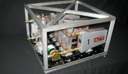
Figure 6 Full-Scale Heat Pipe Loop Systems for Power Electronics Cooling
This prototype HPL has also been tested at various vibration and shock conditions while in operation. As seen in Figure 5, the vibration condition caused the evaporator thermal resistance to decrease. The improved evaporator heat transfer may be due to the more efficient boiling and evaporation heat transfer on the wick surface in the presence of vibration. The shock condition had minimal impact on the evaporator heat transfer. In summary, the prototype HPL design was able to withstand the military-specified vibration and shock conditions without any performance degradation or structural damage.
A Heat Pipe Loop can also have more than one evaporator. ACT has built and tested a Heat Pipe Loop consisting of two evaporators connected in parallel. The dual-evaporator HPL was able to operate successfully and passively (without any control) at various transient, steady-state and startup conditions including uneven heat inputs to the two evaporators.
ACT has built a full-scale power electronic cabinet that consists of twelve Heat Pipe Loops for cooling six circuit boards. This cabinet went through a stringent set of thermal, mechanical, vibration, and shock testing at both ACT and an independent test house before being delivered to the customer in October 2009. Figure 6 shows a photo of the full-scale HPL system.