Large manufacturing plants can occupy thousands of square feet. This becomes a major heating/air conditioning challenge depending on what the company produces. If there is potential for high levels of Volatile Organic Compounds (VOCs) the fresh air supply to the facility may require multiple air exchanges per hour for the safety and health of the workers. More air exchange means higher heating and air conditioning costs. An energy recovery solution is needed.
Problem
In this application, there were two million square feet of manufacturing space requiring multiple DOAS, Dedicated Outside Air System, units ranging from 10,000 – 30,000CFM’s. These units derived cooling from the facility’s large, chilled water plant, and the unit’s heater coils were supplied by the plant’s boiler systems. ACT HVAC Energy Recovery Systems were challenged with meeting several goals from the company’s facility team.
Solution
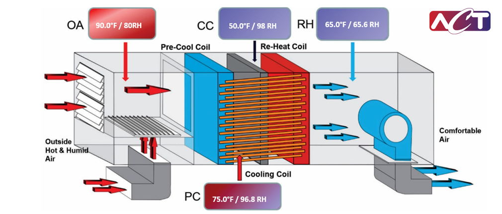
ACT introduced the Wrap-Around Heat Pipe Heat Exchanger, (WAHX) system which when added to a DOAS Air Handler, greatly increases its tonnage cooling capacity passively by removing heat from the incoming outside air and then providing reheat to deliver dry neutral air to the manufacturing space.

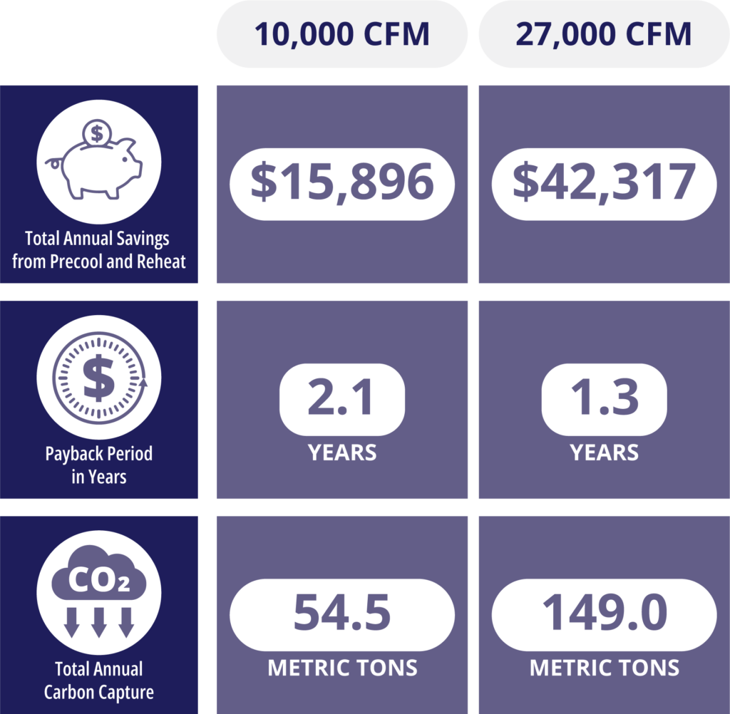
The tonnage and reheat savings are quantifiable by a payback analysis. Payback analysis accounts for the local BIN weather data, local utility rates, and the number of hours that the systems operate. The payback estimate including retrofit installation costs was under 2.1 years for the 10,000 CFM units and 1.3 years for the 27,000 CFM unit.
Carbon emission reduction
An additional benefit ACT’s customer gained was reducing the company’s carbon emissions. This was achieved by ACT’s WAHX reducing the amount of energy consumed when chilling and heating the water for the DOAS air handlers. Large corporations have carbon emissions reduction goals. The facilities group was happy to report that this new system would contribute to that goal and reduce the company’s overall carbon emissions.
Based on the energy savings and carbon reduction goals the team opted for an operational field test of the WAHX Energy Recovery system. Three existing rooftop units were selected. Two 10,000 CFM units and one 27,000 CFM unit.
Payback Estimate for Each Unit

Installation challenges

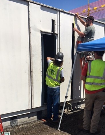
The three units selected were near their replacement age but offered a good basis for the energy recovery testing. A field retrofit of a WAHX system requires two slots to be cut out before and after the cooling coil. Proper installation distances around the cooling coil were maintained to avoid moisture carryover on the highly saturated discharge side of the cooling coil. Additional drain pans are installed under the WAHX precool coil as moisture can condense on this coil.
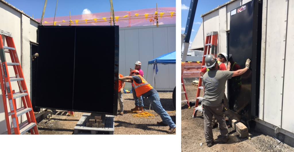
After the slots and drain pan work is completed the WAHX unit is slid into position around the cooling coil. Sheet metal and gasketing is fitted to prevent any air bypass around the cooling coil. The final step is to cover the outside of the WAHX system with an insulated cover. This prevents any condensation issues that could form on the WAHX.
Final Installation Step: Installation of Insulated cover over the WAHX System
In a non-retrofitted WAHX installation, the system sits fully on the inside of the DOAS unit. As with most DOAS WAHX retrofits there is not enough space to internally warp around the cooling coil. This is the main reason for the slotting of the AHU.
The facilities team has instrumented the DOAS AHU to measure savings results in real time. This data will be used to predict plant-wide energy savings as more units are converted or replaced with ACT-WAHX systems.

Rooftop installation of WAXH systems.


