
- Heat Pipe Learning Center
- Pumped Two-Phase Learning Center
- PCM Learning Center
- HVAC Learning Center
- Videos
- eBooks
- Brochures
- Case Studies
- Webinars
Heat Pipe Learning Center
Advanced Cooling Technologies, Inc. is the trusted expert in heat pipe products and technologies. ACT manufactures a large variety of heat pipes, heat pipe heat sinks, and heat pipe assemblies for a wide range of applications in a variety of markets.
In fact, ACT is the only US manufacturer that routinely delivers heat pipes for terrestrial electronics cooling (copper-water), on-orbit satellite thermal management (aluminum-ammonia and copper-water) and high-temperature calibration equipment (liquid metal).
In addition, ACT is the partner of choice in developing new functionality and increased performance with emerging heat pipe technology.
This Heat Pipe Resource page contains the most extensive information on heat pipes and related technology available anywhere on the web, including Fundamentals, Limits, Wicks, Working Fluids and Envelopes, Different Kinds of Heat Pipes, and Advanced Developments.
An Overview of Heat Pipe Technology
Benefits of Using Heat Pipes:
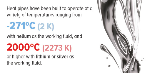
What is the temperature range for a heat pipe?
Individual two-phase systems can carry at least some heat between the triple point and the critical point of the working fluid, but the power transferred near both the triple point and the critical point is very low. There is a smaller practical temperature range that shows individual capabilities and limits, e.g., copper/water heat pipes normally operate between 25°C and 150°C.
Our eXtensive Heat Pipe Resource Center
Latest HEAT PIPE Advancements
HEAT PIPE FAQ

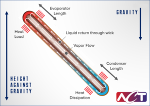
A heat pipe consists of a working fluid, a wick structure, and a vacuum-tight containment unit (envelope). The heat input vaporizes the working fluid in liquid form at the wick surface in the evaporator section.
Vapor and its associated latent heat flow toward the colder condenser section, where it condenses, giving up the latent heat. Capillary action then moves the condensed liquid back to the evaporator through the wick structure. Essentially, this operates in the same way as to how a sponge soaks up water.
Phase-change processes and the two-phase flow circulation in the heat pipe will continue as long as there is a large enough temperature difference between the evaporator and condenser sections. The fluid stops moving if the overall temperature is uniform, but starts back up again as soon as a temperature difference exists. No power source (other than heat) is needed.
In some cases, when the heated section is below the cooled section, gravity is used to return the liquid to the evaporator. However, a wick is required when the evaporator is above the condenser on earth. A wick is also used for liquid return if there is no gravity, such as in NASA’s microgravity applications.
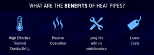
- High Effective Thermal Conductivity. Transfer heat over long distances, with minimal temperature drop.
- Passive operation. No moving parts, and require no energy input other than heat to operate.
- Isothermal operation. Very isothermal surfaces, with temperature variations as low as ± 5 mK.
- Long life with no maintenance. No moving parts that could wear out. The vacuum seal prevents liquid losses, and protective coatings can give each device long-lasting protection against corrosion.
- Lower costs. By lowering the operating temperature, these devices can increase the Mean Time Between Failure (MTBF) for electronic assemblies. In turn, this lowers the maintenance required and the replacement costs. In HVAC systems, they can reduce the energy required for heating and air conditioning, with payback times of a couple of years.
There are some universal benefits of how a heat pipe works across almost all applications.
When asking what a heat pipe is, you’ll get a better understanding by learning about when they are used. You’ll find many simple and complex systems that use these pipes in a variety of deployments based on different operating principles, thermal performance needs, conductivity requirements, spatial restrictions, overall strength, and cost.
Our thermal engineers agree that heat pipes are a smart investment if you have a device or platform that needs any of the following:
- Transfer of heat from one location to another. For example, many electronics use this to transfer heat from a chip to a remote heat sink.
- Transform heat from a high heat flux at the evaporator to a lower heat flux at the condenser, making it easier to remove overall heat with conventional methods such as liquid or air cooling. Heat fluxes of up to 1,000 W/cm2 can be transformed with custom vapor chambers.
- Provide an isothermal surface. Examples include operating multiple laser diodes at the same temperature and providing very isothermal surfaces for temperature calibration.
The most common application is a copper heat pipe system that uses water inside a copper envelope in order to cool electronics, operating within a temperature range of 20°C to 150°C.
One of the benefits of a copper/water system is that it is easy to combine with elements that are already existing in electronics. Heat sinks with heat pipes are present in almost every computing device and have their cooling capabilities enhanced when paired with heat pipes.
HVAC systems often turn to heat pipes for energy recovery because they require no power.
They are also used for the thermal control of satellites and spacecraft. The systems provide an efficient method of heat distribution. These spacecraft systems use extremely pure fluids and are built to meet the strictest of standards, to allow operation for 30+ years. Every issue in space is mission-critical, and small failures can ruin multi-million-dollar equipment.
The total heat load a heat pipe can carry is a function of total length, evaporator and condenser length, diameter, and orientation with respect to gravity. There are several limits that govern heat pipe theory, however, in terrestrial applications the capillary limit is the most limiting factor. This occurs when the capillary pumping capability is not efficient to provide enough liquid to the evaporator from the condenser. This will lead to dryout in the evaporator. Dryout prevents the thermodynamic cycle from continuing and the heat pipe no longer functions properly.
Heat pipes are most capable when the evaporator is below the condenser creating a liquid return path that is gravity aided, and the maximum power decreases as the adverse evaporator elevation is increased.
Now that you have the basics, we’re sure you have more complex questions. While some answers are specific to your needs and system requirements, these responses to standard questions will give you a better understanding of how these devices operate:
- Over what distance can a heat pipe operate?
Earthbound heat pipes that work against gravity are relatively short — typically, a maximum of roughly 2 feet (60 cm) long, and a maximum elevation against gravity of roughly one foot (30 cm).
Spacecraft heat pipes are usually under 10 feet (3 m) long, and the extra length is allowed because they operate in zero gravity.
When a heat pipe works with gravity, called a thermosyphon, the length can be virtually unlimited, and you’ll find many in lengths up to hundreds of feet (m).
- Can a heat pipe operate against gravity?
They can operate even when the evaporator is located above the condenser, going against gravity. This means the capillary action must return liquid against the fluid pressure drops, as well as the gravitational head. This setup will reduce the overall maximum power available to move the working fluid. Use ACT’s Heat Pipe Calculator to see exact requirements and capabilities.
- What is the temperature range for a heat pipe?
Individual two-phase systems can carry at least some heat between the triple point and the critical point of the working fluid, but the power transferred near both the triple point and the critical point is very low. There is a smaller practical temperature range that shows individual capabilities and limits, e.g., copper/water heat pipes normally operate between 25°C and 150°C.
- What materials are used for Heat Pipe envelopes, wicks, and working fluids?
We often get asked what materials envelopes and wicks are made of, and what can be used for working fluids. There are a significant number of materials that can be used for each, but the important requirement is that the fluid and materials must be compatible. We’ve put together this list of compatible materials, but the most common envelope/wick and working fluid combinations are copper/water for electronics cooling, aluminum/ammonia for spacecraft thermal control, copper/Freon and steel/Freon for energy-recovery applications, and superalloy/alkali metalworking fluids for high-temperature applications.
The process of material selection begins with matching your operating temperature to the right working fluid. Proper selection of envelope, wick, and working fluids allows ACT to build you a system that operates maintenance-free.
- Can a Water Heat Pipe Operate After Freezing?
Water heat pipes carry very little power at temperatures below ~ 25°C, due to the very low vapor densities limiting the amount of power that can be transferred. At temperatures below freezing, heat transfer only occurs by conduction through the wall and wick.
Note that properly designed copper/water heat pipes can be designed to withstand thousands of freeze/thaw cycles without damage carrying power after the water is liquid. This is achieved by tightly controlling the liquid inventory so that all of the liquid is contained in the wick. This prevents a liquid bridge from forming and damaging the device by expansion when it freezes.
