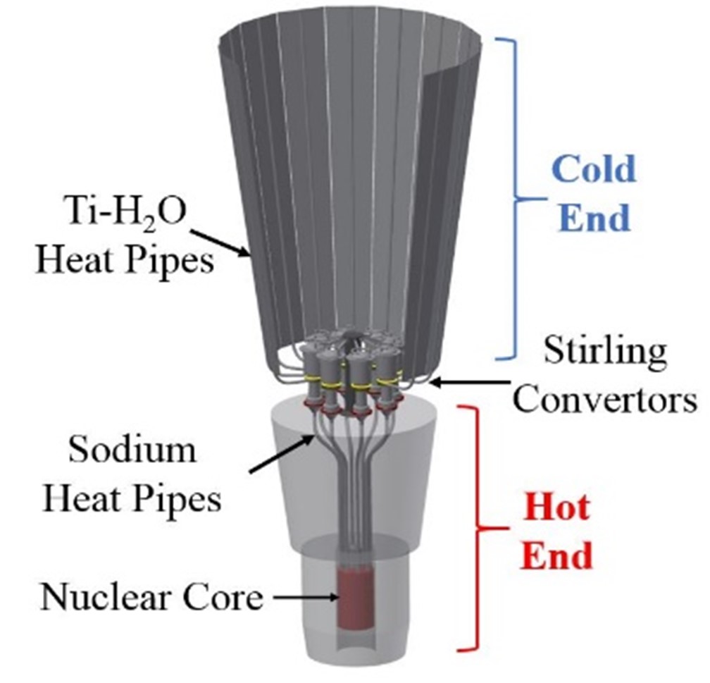
As part of the Game Changing Development (GCD) program within NASA’s Space Technology Mission Directorate, the Kilopower project was a result of NASA GRC’s assessment of small fission power systems for future spacecraft applications and surface missions. These systems are designed to produce 1 to 10 kWe to address the technology gap between Radioisotope Power Systems (RPS), which operate below 500 We, and Fission Surface Power Systems (FSP), which operate above 10 kWe.
The Kilopower design (shown in Figure 1), utilizes alkali metal (sodium) heat pipes to transfer thermal energy from the fission reactor to the Stirling convertor’s heater heads for electrical power generation, and titanium water heat pipes to transfer waste heat from the converter’s cold ends to radiators for ultimate rejection to space. The Kilopower system was designed to operate in space as well as on planetary surfaces.
The heat pipes for the Kilopower system must accommodate four different operating conditions:
- Operation in space under zero-gravity when the condensate (liquid) must return from the condenser to the evaporator only by capillary forces developed in the wick.
- Operation on earth with a slight adverse orientation to estimate the zero-gravity performance. In this case, liquid returns from the condenser to the evaporator also by capillary forces in the wick that would need to overcome the corresponding gravitational forces.
- Operation on the ground in a gravity-aided orientation, for system testing. Liquid returns from the condenser to the evaporator by gravitational forces.
- Restart after exposure to launch orientation – significant adverse orientation. The wick de-primes during launch and must re-prime in space for operation.
In general, surface fission power generation designs include heat pipes that take advantage of gravity to reliably return the condensate to the evaporator. These heat pipes are widely known as thermosyphons, and therefore, are unable to work in space (microgravity) environments. The Kilopower system, however, uses wicked heat pipes enabling both surface and space operation. ACT’s involvement in the thermal management of the Kilopower system included the development of both the heat pipes for the hot end of the system and the heat pipe radiator for the cold end of the system.
kilopower’s hot end
For the hot end of the Kilopower system, ACT’s first objective was to develop alkali metal heat pipes (with sodium as working fluid) containing various types of wicks that would allow the system to operate in both microgravity and planetary surface (gravity assisted) environments. A second objective was to develop two sets of sodium heat pipes to be used by the actual Kilopower system during various stages of its development.
During a NASA Phase I SBIR, ACT performed feasibility studies for heat pipes with three types of wicks that would be suitable for Kilopower: groove wicks, traditional arterial wicks, and self-venting arterial wicks. Sintered arterial heat pipes have traditionally been specified for this application due to their ability to transport large powers over long distances, but if vapor or Non-Condensable Gas (NCG) is generated in the artery due to radiation it would cause the heat pipe to de-prime and, consequently, to fail to operate. Self-venting arterial and grooved heat pipes have an advantage over sintered arterial heat pipes due to their ability to allow the trapped vapor or NCG to escape into the vapor space. During the above-mentioned program, a 1m (39.67in) long, 0.75in (1.91cm) outer diameter self-venting arterial heat pipe and a grooved heat pipe were developed [20]. Thermal performance testing of the two heat pipes was conducted at 725°C while the adverse elevations varied from 0.1in (0.25cm) to 5.0in (12.7cm). The self-venting arterial heat pipe transported at least 2.6kW of power at all adverse elevations except 5.0in (12.7cm) where it transported only 1.4kW. The grooved heat pipe could transport only 846W at 0.1in (0.25cm) elevation and 346W at 1in (2.5cm).
During the two follow-on NASA Phase II SBIRs several heat pipes were fabricated and tested for the Kilopower program (hot end of the system), including self-venting arterial heat pipes, thermosyphons, and a hybrid screen-groove heat pipe. The self-venting arterial heat pipes carried sufficient power while straight but were unable to meet the transport requirements after bending.
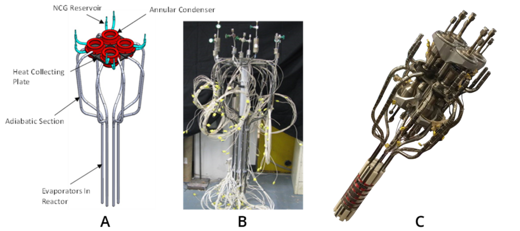
Two sets of thermosyphons were fabricated and delivered to NASA Glenn for integration into Kilopower test setups for two stages of the development. Figure 2a shows a CAD drawing of the first set of heat pipes integrated with the heat collecting plate that was the conduction-based interface between all eight doughnut-shaped condensers and the eight Stirling converters (and simulators) heater heads. Observe that the eight heat pipes have small reservoirs (as extensions of each condenser) containing argon that assists the heat pipes during startup. Two of the eight reservoirs are larger than the other six to allow the shutdown of the two corresponding heat pipes to simulate heat pipe failure during system testing. Figure 2b shows the fabricated first set of Kilopower heat pipes, ready for delivery to NASA GRC. Figure 2c shows the second set of heat pipes, also integrated with the heat-collecting nickel plate, as displayed by NASA at the 2018 Nuclear Emerging Technologies for Space Conference (NETS) in Las Vegas, NV.
First Set – Results
Nine heat pipes (thermosyphons) were developed as the “first generation” and delivered for the Kilopower program. The pipes were intensively tested before delivery [27]. The performance for each of the nine thermosyphons is shown in Table 1. The measurements were performed in ambient, and the measured heat loss was 570W. Since the performance requirements were met, as seen in the table, dry-out was not further attempted/reached for any of the heat pipes.
Thermosyphon startup: Alkali metal heat pipes are known for having difficulties at start-up due to several reasons:
- the necessary superheat to initiate boiling
- the low sonic limitation that chokes the pipe during its temperature increase towards the operating point
- the potential freezing of the working fluid in the condenser
Adding NCG inside the heat pipe is a typical method that addresses start-up difficulties. This gives a shorter effective heat pipe length during start-up since the NCG blocks most of the adiabatic section. However, in the heat pipes under discussion, the presence of NCG did not mitigate entirely the start-up related temperature spikes.
| Pipe No. | Electric Power | Net Power | Dry Out |
| 1 | 1250 | 680 | No |
| 2 | 1250 | 680 | No |
| 3 | 1200 | 630 | No |
| 4 | 1050 | 480 | No |
| 5 | 1150 | 580 | No |
| 6 | 1250 | 680 | No |
| 7 | 1200 | 630 | No |
| 8 | 1250 | 680 | No |
| 9 | 1200 | 630 | No |
An example is shown in Figure 3 [27]. The heat pipe started successfully, but still required a very large amount of superheat in the evaporator before starting up which is very common with a deep alkali metal pool. In May 2016, the first generation thermosyphon cluster was tested at NASA Glenn Research Center in an electrically simulated reactor. The start-up and steady performance results of the heat pipes were positive.
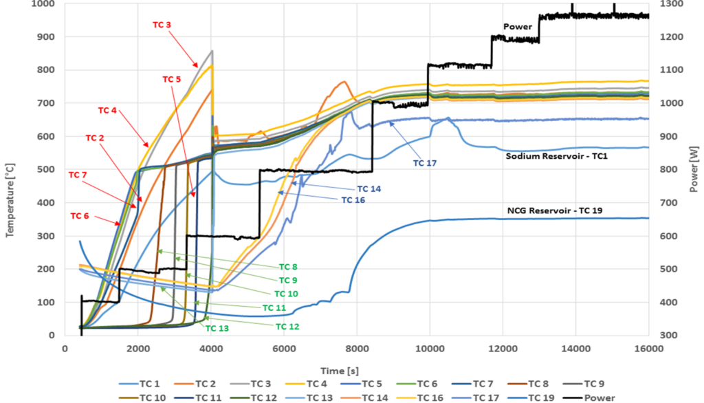
The large temperature spikes observed during start-up when the heat pipes were tested individually at ACT did not occur. The thermal mass of the simulated reactor and heat transfer method at the heat pipe evaporator contributed to these results. When tested at ACT, the heat pipe evaporators were exposed to individual radiation-based heaters; when integrated into the reactor simulator at NASA, the evaporators were heated by conduction limiting their exposure to high temperatures and preventing the startup-related temperature spikes.
Second Set – Results
This was delivered in October 2016 for testing on a depleted uranium-based system at NASA GRC. Two modifications were made to the second set to improve the startup behavior of the sodium thermosyphons: an additional screen-wick in the evaporator and adjustments in the geometry of the pipe to reduce the required charge volume. The additional screen in the evaporator filled the inner diameter almost entirely except for a 3.2mm (0.125 in.) diameter hole in the center for vapor venting. The additional portion of the screen wick (with the role of retaining the entire amount of liquid before freezing) had a larger pore size allowing the primary wick to further retain the liquid after startup and during normal operation.
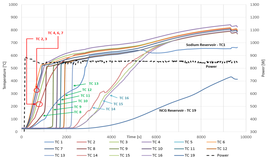
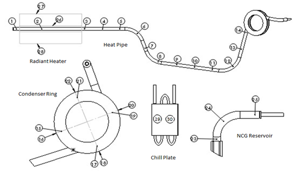
The startup performance of the Second Set (generation) thermosyphon is shown in Figure 4 where the noticeable smooth startup confirms the benefits of the newly inserted wick in the evaporator. The instrumentation layout is shown in Figure 5.
Kilopower’s Cold End
Under SBIR Phase I/Phase II programs, ACT developed a series of freeze/thaw tolerant titanium water heat pipes with aluminum radiator face-sheets attached to reject the waste heat of a small-scale space nuclear fission power system (i.e. Kilopower system) [28-31]. Since the system is designed to operate in both microgravity and on planetary surfaces (with potential freeze/thaw cycles), the titanium heat pipes have hybrid wicks consisting of a bi-porous screen structure in the evaporator and an axial groove structure in the adiabatic and condenser sections. Figure 6a shows the grooved heat pipe in its final shape. After bending, multiple grooved pipe sections (Figure 6b) were joined together through electron beam welding. The full-length (~1m) grooved pipe was then coupled with the bi-porous screened evaporator (Figure 6c) through the screen-groove hybrid joint. The heat pipe was charged with deionized water, and a small amount of argon (NCG) to facilitate the startup and the freeze/thaw processes.

Testing results showed good heat transfer capability and isothermality in a slightly unfavorable (3 mm) gravity orientation of the heat pipe. Its freeze/thaw tolerance feature was also demonstrated. As the plot from Figure 7 shows, the prototype was first operated at a steady state at 125°C working temperature with 250W heat input (state 1).
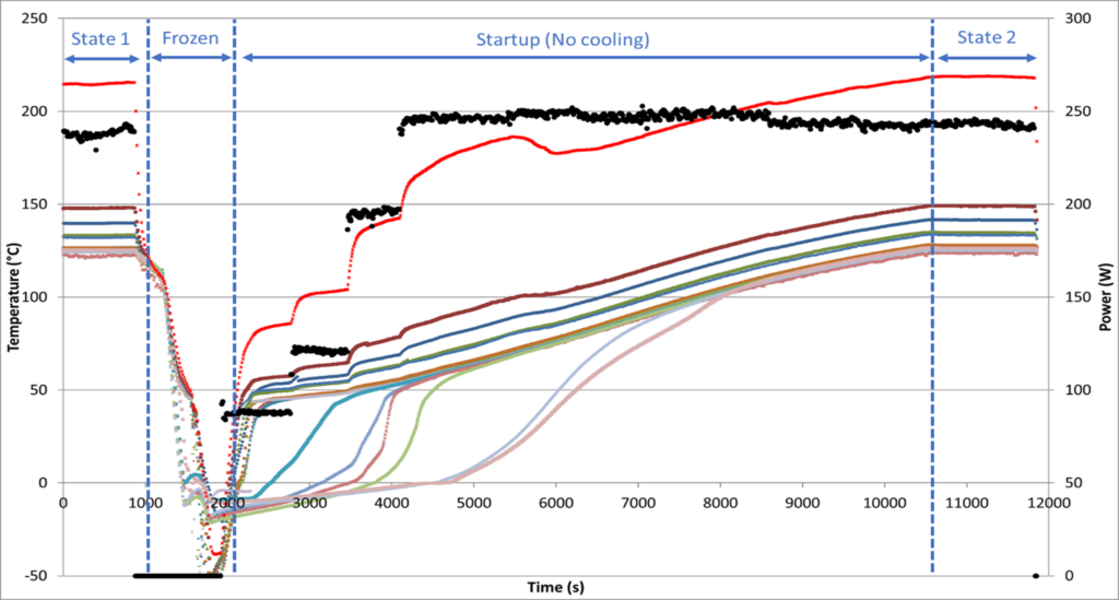
After 1000 seconds, the heat input was removed, and the entire system was cooled to -50°C. At 2000 seconds, heat was re-applied to start up the pipe, incrementally increasing from 125W to 250W. As the figure shows, a smooth freeze/thaw recovery curve was obtained. As the working temperature reached 125°C at t=10500 seconds, the active cooling was turned ON again to maintain the working temperature. As it can be observed, the heat pipe fully returned to the initial steady state parameters (state 1). This test demonstrated that both the bi-porous screen wick evaporator design and the charged amount of argon enable the survival and startup from frozen conditions.
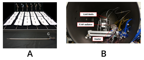
An additional seven titanium water heat pipes with different evaporator configurations to accommodate the cold end geometry and various grooved pipe lengths were fabricated and tested. Six of the heat pipes became heat pipe radiators by integrating them with aluminum face-sheets through S-bonding. They were tested in thermal vacuum chamber. All six heat pipe radiators (shown in Figure 8a) successfully carried 125W of waste heat at the working temperature of 400K and rejected the heat into the vacuum environment through radiation as shown in Figure 8b.
Learn More about ACT’s Work in Research & development
Visit www.1-act.com/engineering-services/research-development/ to see what our R&D team is currently working on. To learn more about ACT’s work in the Energy industry, visit: https://www.1-act.com/industries/energy/


