
A BRIEF OVERVIEW OF HEAT PIPE DESIGN GUIDELINES
Copper/water heat pipes have a copper envelope, use water as a working fluid, and typically operate in the temperature range of 20 to 150°C. Heat pipes are an extremely effective method of reducing hot spot temperatures and increasing allowable power in a system by moving heat to an external sink or spreading heat along a surface. ACT manufactures copper/water heat pipes from the following standard tube sizes (outside diameters) which are readily available:
- 3, 4, 5, 6 and 8 mm
- 1/8, 1/4, 3/8 and 1/2 inch
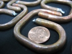
ACT can also create custom heat pipes outside of these diameters. ACT can bend and flatten to the following specifications. Please note that these values are guides, not limits. ACT has designed heat pipes below these values.
- The typical bend radius is greater than 3 times the heat pipe O.D. Bend Radius > 3 x OD of the heat pipe
- Flatten ~ 2/3 x OD of the heat pipe
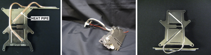
Figure 2. (a) Heat pipes can be used in an assembly to cool discrete components by moving heat off the chip to a remote heat sink. (b) Heat pipes can also be used in “block-pipe-block” configurations, where the evaporator and condenser of the heat pipe are embedded in blocks attached to the electronics and the heat sink. (c) Another example of heat pipe bending.
ACT very rarely provides customers with stand-alone heat pipes. With the increased demand for system-ready solutions, ACT manufactures custom assemblies developed specifically for each customer’s design requirements. Heat Pipes are easily integrated into system designs because of their ability to form to intricate geometries; see Figure 2. Heat pipes are not structural elements but can be embedded in assemblies to form a high-conductivity or HiK™ plate.
ACT engineers will work with customers to properly integrate heat pipes into a system to minimize thermal resistance and maintain system integrity. ACT is experienced in soldering heat pipes as well as using thermal epoxies as an attachment technique. ACT Engineers are available to advise on which solution is best for your application.
At ACT, we guarantee quality and reliability for our heat pipes by our certified manufacturing procedures. All our heat pipes are subject to thermal testing before being delivered to the customer. ACT also has the capability to validate our heat pipe performance under the following conditions:
Freeze/Thaw in Heat Pipe Technology
Heat pipes utilize a wick structure to transport the liquid working fluid from the condenser to the evaporator. When properly made, the working fluid fully saturates the wick without making a puddle of excess fluid. With the fluid completely contained within the wick, it is not able to bridge the gap across the inside diameter of the heat pipe. This allows multiple freeze-thaw cycles to occur without heat pipe deformation. A variety of working fluids may be used which directly affects the freezing temperature of the heat pipe.
ACT routinely subjects heat pipes to thermal cycling to meet customer requirements. Typical freeze-thaw tests are conducted from temperatures ranging from -20 to +20°C and -45 to +125°C. ACT has tested heat pipes up to 1,200 cycles, but the number of cycles is typically customer-driven. When freeze/thaw screen is typically conducted with as little as 10-20 cycles. Heat pipes may be thermally cycled prior to installation into assemblies. Heat pipe assemblies are also thermally cycled in assembled units to assure system-level performance.
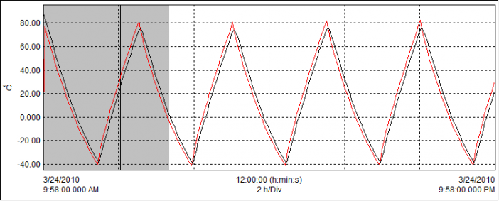
Figure 8: Typical Heat Pipe Freeze/Thaw cycle data.
Examples of Freeze-Thaw Testing in Heat Pipe Technology
Heat Pipes – ACT conducted tests to collect data on heat pipe thermal cycling survivability. The data set for these experiments used both fabricated flattened and bent 4mm heat pipes as well as 0.25” diameter copper water heat pipes. Heat pipes were exposed to as many as 1200 freeze-thaw cycles without deformation or performance degradation
AlSiC HiK™ Plates – This project developed an innovative low-CTE heat spreader by embedding heat pipes into AlSiC plates. These plates showed similar effective thermal conductivity before and after 100 freeze/thaw cycles from -55°C to 125°C.
Aluminum HiK™ Plates – In this project, copper water heat pipes are soldered into aluminum plates. Prior to fabrication, the heat pipes are screened by being exposed to 300 cycles from -20°C to +20°C. Once the assemblies were fabricated, the plates were exposed to an additional 50 cycles from -40°C to +75°C in two different orientations (100 cycles total) to assure freeze/thaw survivability. The graph above shows the temperature profile of HiK™ plates exposed to thermal cycling. 100% of the parts were tested, and all assemblies must pass prior to shipping. All plates are checked for any signs of thermal or mechanical degradation.
Heat Pipes and Frozen Start-Up
Many military and commercial applications specify temperatures ranging from -45˚C to + 70˚C. Water heat pipes are typically used in these applications because of their proven reliability and capability. Water heat pipes operate at full capacity at the higher end of the temperature range, but their maximum power drops off as the temperature is reduced, with 25°C being a rough lower limit for water heat pipe operation; see Water Operating Temperature Range for more details. Below 0°C, the water in the heat pipe is frozen, and heat removal is by conduction only. This is generally not a problem for electronics cooling, since the primary concern is to maintain the electronics below a maximum temperature. When the system starts up from a colder condition, say -40°C, the electronics will warm up until the power is around 25°C, and the heat pipe starts operating. Properly designed heat pipes can operate after thousands of freeze/thaw cycles. If heat pipe operation below 25°C is required, then the thermal designer can switch to a different working fluid such as methanol
A frozen start-up can be an issue if the system’s thermal mass and heat transfer are such that the fluid in the evaporator is thawed and vaporized by the heat input, travels to the condenser and freezes there. This could result in the depletion of fluid in the evaporator, eventually shutting down the heat pipe. This is a system design issue and not typically a heat pipe limitation. There are four ways to address this issue. First, design the system so that a frozen start-up is not an issue. In other words, the input power and vapor transport are sufficient to thaw the entire system. Second, use active controls such as turning off fans to limit heat transfer in freezing conditions. Third, design in a secondary heat transfer mechanism so that the heat pipes are not needed to prevent the device from overheating in freezing ambient conditions. Fourth, add a predetermined amount of non-condensable gas (NCG) to the heat pipe to ensure “orderly” freezing and thawing; Gas Loaded Heat Pipes for Start-Up from a Frozen State for more details. Options one and three are typical in most assemblies, by default, but can be ensured through analysis and testing.
Designing Heat Pipes for Shock & Vibration
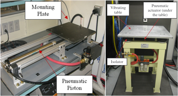
ACT has substantial experience in designing, fabricating, and testing heat pipe assemblies to various shock and vibration loadings. ACT has in-house mechanical shock and vibration test equipment as shown in Figure 1. ACT’s heat pipes and loop heat pipes have been tested to diverse shock and vibration conditions including:
- 4,500 lbf force sustained vibration loads
- Up to 9,000 lbf shock loads
- 0-3,000 Hz Frequency Range
- Over 100g’s peak acceleration
- Vibration: Sine, Random, Sine on Random, Random on Random
- Shock: Haversine, Half-Sine, Saw-Tooth, & Trapezoid
- Replication of Measured Field Data
- Gunfire Vibration
- Shock Response Spectrum
Shock & Vibration Test Examples at ACT
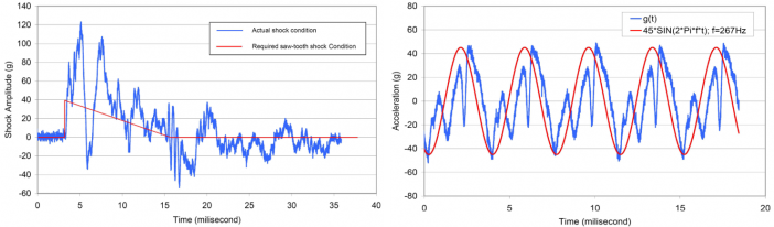
ACT’s shock test rig (Fig. 1) can produce a peak acceleration of Gpk=123g. The vibration capabilities include a frequency of 267 Hz, Grms=24g, and Gpk=45g. Examples of shock and vibration test profiles are shown in Figure 2. Testing has confirmed that vibration loading has little or no impact on the performance of ACT’s heat pipes. Shock and vibration testing showed no evidence of overstress or fatigue on the heat pipes or solder joints.
Hybrid Two-Phase Loop System
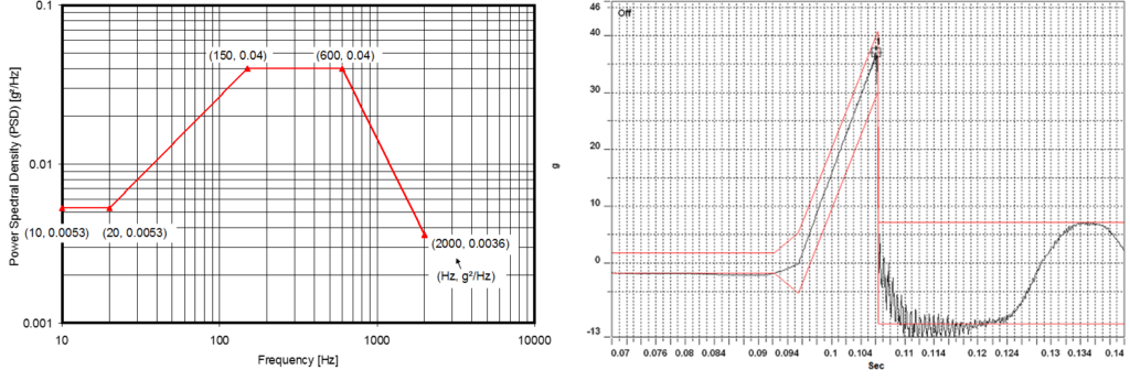
ACT engineers and technicians tested a pumped two-phase system with internal wick components to military vehicle shock and vibration requirements. Figure 3 (a) shows the PSD profile of the body and frame in a Future Combat Systems (FCS)-like a military vehicle. The PSD curve produces a maximum vibration level of about 5 Grms. Figure 3 (b) shows the shock profile of the same vehicle with a half-sine pulse of 10 G’s for 50~75 ms. This thermal performance was identical before and after the tests.
Heat Pipe Loop Assembly
This assembly was tested to the shock and vibration specifications shown in Figure 3 under full thermal loading with no degradation in performance during testing.
ACCELERATION
Dual heat pipes for high accelerations. One set of the heat pipes always operates, since the acceleration returns the condensate to the evaporator.
As long as the wick’s capillary force is greater than the pressure drops and the acceleration loading, the heat pipe will perform properly under various acceleration loadings. However, extremely large adverse acceleration loadings may overwhelm the wick’s capillary capability, de-priming the wick or eventually causing the wick to dry out.
If the acceleration is for short durations, the wick structure will re-prime and the thermal transient may be within an allowable range. An alternative approach will be required if the transients are for longer durations. If the axis and direction of acceleration are known the heat pipes can be configured such that acceleration helps return the condensed fluid “gravity aided”. If the acceleration axis is unknown heat pipes can be arranged in pairs so that regardless of the acceleration vector one heat pipe will always be “gravity aided”; see graphic at below.
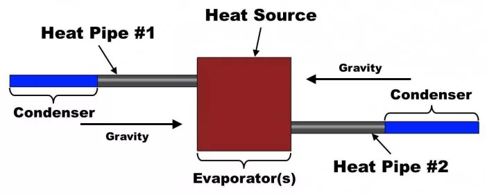
Dual heat pipes for high accelerations. One set of the heat pipes always operates, since the acceleration returns the condensate to the evaporator.
HEAT PIPE TRANSPORT
The total heat load a heat pipe can carry is a function of total length, evaporator and condenser length, diameter, and orientation with respect to gravity. There are several limits that govern heat pipe theory, however, in terrestrial applications the capillary limit is the most limiting factor. This occurs when the capillary pumping capability is not efficient to provide enough liquid to the evaporator from the condenser. This will lead to dry out in the evaporator. Dryout prevents the thermodynamic cycle from continuing and the heat pipe no longer functions properly. Heat pipes are most capable when the evaporator is below the condenser creating a liquid return path that is gravity aided, and the maximum power decreases as the adverse evaporator elevation is increased; see Figure 3. The maximum adverse elevation for a water heat pipe is roughly 25 cm (10 inches). ACT will use worst-case orientation in its heat pipe designs to assure the design will operate.
Though the total power is affected by orientation, thermal heat pipe characteristics are not. For instance, the effective conductivity and thermal resistance of a heat pipe are simply a function of diameter and overall length. As long as the heat pipe can operate at a given temperature and power, it should see effective conductivities of about 50,000 – 200,000 W/mK. This range is a function of overall length with longer heat pipes having higher effective conductivities. Heat pipes are convection devices however, through modeling and testing, ACT has proven these effective conductivities.
ACT has a proven track record of designing and manufacturing heat pipes for any suitable application. For additional help in designing with heat pipes please email one of our capable engineers at solutions@1-ACT.com or call us at (717)-295-6061.
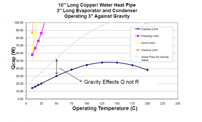
Figure 3. Elevating the evaporator above the condenser reduces the maximum power that the heat pipe can carry. It does not affect the heat pipe resistance.

