

PCM Heat Sink Design Considerations
The thermal conductivity of PCMs can be as low as 0.15W/m K, so the allowable power into a block of PCM is very low. To increase the maximum power capability, the effective thermal conductivity of the PCM must be enhanced. As shown in Figure 1, folded fins are often used. In larger PCM heat sink, heat pipes may also be added to increase the effective thermal conductivity.
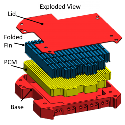
Figure 1. PCM Heat Sink Schematic
The design process block diagram below details the key individual steps. First the transient heat load (power and time) is established. This determines the required PCM reservoir sizing. This is followed by an iterative design sequence reviewing fin design and structural analysis that ultimately results in the final design. This transient thermal modeling confirms the heat transfer to/from the PCM, identifies the location of the PCM Melt front overtime to ensure adequate PCM is present to handle the full transient load, and calculates the overall system ΔT to make sure the devices are not overheating.
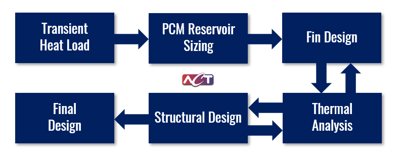
Figure 2. PCM Heat Sink Design Process
Fins are generally used to increase the effective thermal conductivity into the PCM, typically with copper (K ~ 400 W/m K) or aluminum (K ~ 200 W/m K) fins. As shown in Figure 3, most of the heat travels up the high-conductivity fins, and then into the PCM. The high conductivity and large surface area of the folded fins increase the maximum power that can be applied to the heat sink.
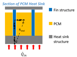
Figure 3. Copper or aluminum fins increase the effective thermal conductivity into the PCM
After the power and thermal storage, time targets are used to determine the volume of PCM required, there are two primary challenges arise associated with the design of a PCM module. The first is designing around the poor thermal conductivity of PCM. Wax-based PCM has thermal conductivities between 0.2 and 0.3 W/m-K. Simply filling a container with PCM and applying a heat load would create a large temperature rise as the PCM melts. The second challenge is managing voids at the location of critical heat loads. As shown in Figure 3, a void volume is present to allow for expansion of the PCM during phase transition. In most cases, where orientation with respect to gravity varies, the location of the PCM, when it melts and freezes, will vary as well. If there is a significant empty space around a critical component, that component can see a large temperature rise before the PCM absorbs the heat load.
The solution to both of these challenges is in the design of internal conduction paths, which typically are fins internal to the heatsink. As you can see by the thermal resistance network outlined in Figure 3, conduction will play a large role in assuring the PCM melts without significant temperature rise.
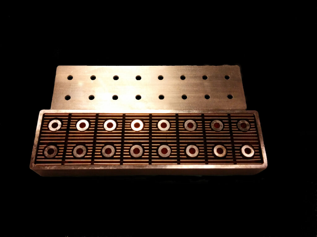
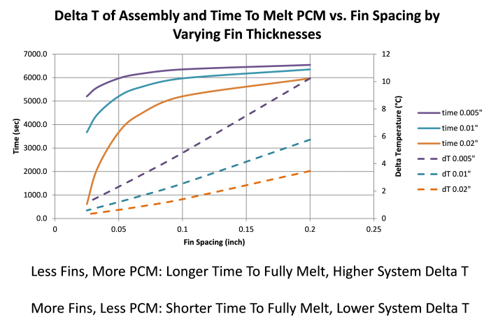
Figure 4. PCM Heat Sink Example
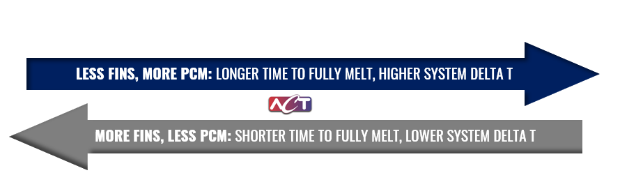
The fin spacing or fin pitch and thickness of the fins are critical design considerations. Figure 4 is an example of the trade-offs using different fin pitches and thicknesses. The solid line shows time to melt, or thermal storage capacity, for a given power on the left axis. The matching colored dashed line is the corresponding thermal gradient through the fin and PCM shown on the right axis. Both curves are a function of fin spacing. As you can see, there is a trade-off between thermal storage capacity and delta T. As you add more fins you reduce your thermal gradient, but displace more PCM which reduces thermal storage.
A scenario with too few fins is shown toward the left side of Figure 4. At the other extreme, the spacing between fins is large to maximize the volume of PCM, but thermal gradients are large due to the poor conductivity of the PCM. This occurs toward the right side of the plot. For the heat load and geometry used to generate these curves, the optimum fin spacing is between .05 to .10 inches. This is where marginal gains in thermal storage capacity are observed as fin pitch is increased. Optimizing the fin pitch and thickness assures that all PCM is melted with a minimal thermal gradient, thereby maximizing the performance of the heat sink.
PHASE CHANGE MATERIAL (PCM) PRESSURE AND VOID CONSIDERATIONS
A schematic of the PCM Heat sink module structure is seen in Figure 5. Internal features include PCM, fin structure and void allocation. During manufacturing, a heat sink module will be completely leak tight which makes it a pressure vessel. Since the PCM volume increases when the PCM melts, a void volume, typically 8 to 15 percent of the total volume, is required to prevent the PCM from bursting.
One of the challenges is assuring the void volume does not cause unwanted temperature rise, and fortunately, this design challenge is resolved by the proper fin design that we discussed above. Since the fins will provide a good conduction path to get heat into the PCM, the temperature rise is minimal even if there is a small void directly above a large heat-generating component.
When dealing with high heat fluxes in discrete locations, management of molten PCM flow must also be considered in the design. Localized heat input can produce high-pressure gradients as PCM melts, expands, and yields the surrounding solid PCM. Enhancing heat spreading, with heat pipes for example, can reduce this effect by uniformly melting the PCM. Flow configurations that allow the PCM to move easily during melting have also been developed.
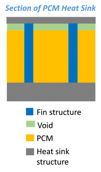
Figure 5. PCM heat sinks include a void volume to accommodate the expansion when the PCM melts
PHASE CHANGE MATERIAL (PCM) PRESSURE AND VOID CONSIDERATIONS EXAMPLE
After selecting the PCM, determining the required volume and designing the enclosure with proper fin and wall structure, it’s time to manufacture and test the PCM heat sink. The estimated PCM properties are shown in Table 3. Note the large changes in specific heat for the different temperatures. For modeling, the latent heat has been modeled as a large specific heat, which is the amount of heat per unit mass required to raise the temperature of a material by 1°C. The reason why PCMs are so effective is that during phase transition, there is a dramatic increase in the effective specific heat. As you can see there is an order of magnitude increase from approximately 1,600 Joule per kilogram degree kelvin as a solid to over 60,000 at its melting temperature between 72.2 and 75.9 °C.
Table 3. PCM Properties for Tested Sample
| Liquid Density | 0.8 kg/L |
| Solid Density | 0.857 kg/L |
| Thermal Conductivity | 0.2 W/m K |
| Specific Heat | |
| < 72.2 °C (solid) | 1,657 J/kg K |
| 72.2 to 75.9°C (melting | 60,286 J/kg K |
| > 75.9°C (liquid) | 2,379 K/kg K |
Figure 6. PCM heat sink test apparatus
The heat sink test setup is shown in Figure 6. Heat is applied with the two heaters on either side of the center. Test results are shown in Figure 7. As indicated by the solid black line at the top of this graph, slightly over 40 W of power was applied. If you’re familiar with PCM, you’ve probably seen the blue theoretical line. Basically, the module heats up until it reaches the PCM melt temperature. It can then hold within a few degrees of that temperature until nearly 100% of the PCM has melted. Once all the PCM is melted the temperature begins to rise at the rate dictated by the specific heat. In this case, the PCM heat sink was designed to absorb the heat load for about 250 seconds, with some margin. The red-tested results matched fairly well and the theoretical temperature was never exceeded.
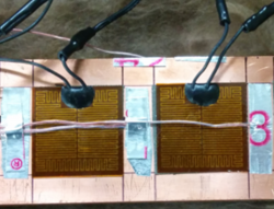
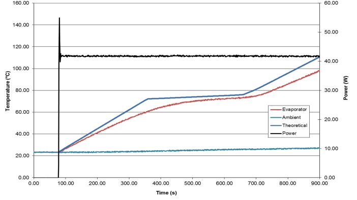
Figure 7. Thermal Storage Test Results, Comparing Measured and Predicted Heat Sink Temperatures
