Most thermal storage systems are designed to store heat by melting a Phase Change Material (PCM). They are then recharged by freezing the PCM. Such liquid/solid systems can operate over a very large number of cycles. When only a few cycles must be handled, Thermal Storage with Venting should be considered, since it can result in lighter and/or more compact systems.
thermal storage with venting
Most thermal storage systems are designed to store heat by melting a Phase Change Material (PCM). They are then recharged by freezing the PCM. Such liquid/solid systems can operate over a very large number of cycles. When only a few cycles must be handled, Thermal Storage with Venting should be considered, since it can result in lighter and/or more compact systems.
Sublimators have been used for many manned spacecraft and space suits, going back to the Apollo program. Liquid water is pumped through a heat exchanger to remove the waste heat. The heated water is then pumped through the sublimator, which consists of tubes in contact with porous media. The outer walls of the porous tubes are exposed to the vacuum of space. A portion of the water freezes in the porous media, cooling the remaining liquid water. The ice also prevents liquid water from exiting through the porous media. The ice gradually sublimes (changes directly to gas), add additional water freezes, so the cycle can continue.
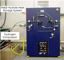
Figure 1. Metal hydride thermal storage system designed for multiple venting cycles.
The one major drawback to sublimators is that they only work when the outside pressure is very low (below the triple point of water, 611 Pascals). To overcome this restriction, ACT has developed Thermal Storage Systems with Venting that can operate even at atmospheric pressure. Examples include:
- Single-Use Vapor Venting Systems (One to a Few Cycles) When heated, liquid held in a porous structure boils, vaporizes, and then the vapor is vented.
- Hydride Thermal Storage Systems use metal hydrides, which desorb hydrogen when heated.
Note that “Single Use” vapor venting and hydride venting systems can be recharged, and then be reused.
The mass and/or volume can be reduced considerably for a venting system when compared with a non-venting PCM thermal storage system; see Table 1. Four systems are compared, all of them designed to handle 1.8 MJ:
- Paraffin Wax Thermal Storage
- Methanol Venting System, with a 45% porosity copper wick
- Methanol Venting System, with a 45% porosity carbon wick
- Hydride Venting System
The methanol with a copper wick weighs more than the PCM system but takes up only one-quarter of the volume. If a carbon foam wick is used, then the system has one-third of the mass, and one-quarter of the volume. Finally, the hydride system has one-half of the mass of a PCM system, but only 7% of the volume.
Comparison of Mass and Volume for PCM, Methanol Venting, and Hydride Venting Systems
| Heat Energy | System | Mass | Volume |
| 1 kW for 30 min = 1.8 MJ | Paraffin Wax | 20.5 kg | 26.6 liter |
| Methanol / Copper Wick | 31.4 kg | 7.17 liter | |
| Methanol / Carbon Wick | 6.89 kg | 7.17 liter | |
| Hydride | 10.3 kg | 1.69 liter |
SINGLE-USE VAPOR VENTING SYSTEMS FOR THERMAL STORAGE (ONE TO A FEW CYCLES)
Most thermal storage systems are designed to store heat by melting a Phase Change Material (PCM). They are then recharged by freezing the PCM. Such liquid/solid systems can operate over a very large number of cycles. When only a few cycles must be handled, Thermal Storage with Venting should be considered, since it can result in lighter and more compact systems when compared with a non-venting PCM thermal storage system; see Table 2. The first venting system assumes a 45% porosity copper wick (current technology). The mass could be further reduced by developing a lighter, 45% porosity carbon wick. The methanol with a copper wick weighs more than the PCM system but takes up only one-quarter of the volume. If a carbon foam wick is used, then the system has one-third of the mass and one-quarter of the volume.
Comparison of Mass and Volume for PCM and Methanol Venting Systems
| Heat Energy | System | Mass | Volume |
| 3 kW for 45 sec = .0135 MJ | PCM | 1.5 kg | 2.0 liter |
| Methanol / Copper Wick | 2.36 kg | .54 liter | |
| Methanol / Carbon Wick | .52 kg | .54 liter | |
| 1 kW for 30 min = 1.8 MJ | PCM | 20.5 kg | 26.6 liter |
| Methanol / Copper Wick | 31.4 kg | 7.17 liter | |
| Methanol / Carbon Wick | 6.89 kg | 7.17 liter |
The most commonly used vapor venting system is the Sublimator, which uses a liquid-ice-vapor transition to remove heat from manned spacecraft and space suits, going back to the Apollo program. The one major drawback to sublimators is that they only work when the outside pressure is very low (below the triple point of water, 611 Pascals). To overcome this restriction, ACT has developed Thermal Storage Systems with Vapor Venting that can operate even at atmospheric pressure. Thermal energy is captured as latent heat by evaporating a liquid and the vapor is then vented from the system. A schematic of the system is shown in Figure 1. A fluid chamber is attached to the heat source which is to be maintained within the given temperature range. The interior of this chamber contains a wick structure. Prior to use, the chamber will be charged with a specified quantity of the working fluid such that the entire liquid inventory is contained within the wick. A transport line connects the chamber to the ambient and is controlled by a series of valves.
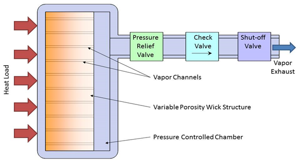
Figure 2. Wick-based Evaporation/Vapor Venting Cooling Concept.
As heat is applied to the chamber, the liquid in the wick will evaporate, raising both the temperature and pressure within the chamber. The vapor will flow through channels in the wick away from the heat source. As the pressure increases within the chamber the pressure control valve will open allowing vapor to be vented off. The pressure will then drop and the valve will close. The valve will continue to pulse open and close to maintain the pressure for which the valve is set. Since the fluid contained within the chamber is two-phase at saturation conditions, the temperature is directly related to this pressure. This relationship allows the temperature to be set and maintained within a narrow range that is determined by fluid properties, as well as the lift and seat pressure of the control valve.
Several other optional valves can be included to increase the versatility of the system. For long-life storage, a rupture disk would be installed downstream from the pressure control valve. This disk would prevent leakage of the working fluid, and minimize corrosion of the pressure control valve. For a system that is designed for venting to vacuum or low pressures found at high altitudes a check valve can be included to ensure that ambient air is not pulled into the chamber before the correct ambient condition is reached. If the system will be exposed to temperatures above the set point during storage but will be pre-cooled to below the set point before the beginning of the mission, then the shut-off valve can be included to prevent venting fluid before it is required. In this case, a second rupture disk may be included on the chamber for pressure relief as a safety precaution to prevent the chamber from bursting if exposed to extremely high temperatures. If either rupture disk is broken, then the system would need to be recharged before use.
Vapor-vented thermal storage system Applications
- Missions with multiple cycle operations (can be recharged)
- Volume and weight-constrained systems
- High heat load and short time durations
- Large lateral and normal G-loading environments
- Long duration storage
- Hydrides can also be used
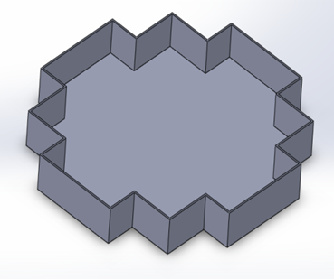
Figure 3. Vapor-Vented Thermal Storage System
The vapor-vented thermal storage system is currently at Technology Readiness Level (TRL) 6, System Prototype Demonstration in a Relevant Environment. ACT has already demonstrated a vapor-venting system, using methanol as the working fluid, and shown that it can dissipate 1 kW for 120 seconds:
- Suitable for high g-loading
- Maximum weight: 1.5 lbs.
- Limited Volume: 0.4 L
- Copper wick
- Easy to vent for testing, and then refill
VAPOR VENTING- Comet Sample Return
A vapor venting refrigeration system is a form of semi-active cooling where heat is removed from the system via the periodic vaporization and venting of a working fluid. The fluid is maintained in a two-phase saturated state where the vapor pressure is a function of only vapor temperature. Heat is absorbed via the latent heat of vaporization of the working fluid raising the temperature and pressure. At a predetermined setpoint, a valve is opened venting vapor to the environment and removing heat from the area to be cooled. The venting lowers the pressure and temperature of working fluid allowing the process to be repeated.
Compared to active refrigeration systems (such as vapor-compression cycles), vapor venting is simple and lightweight, requiring only the opening and closing of valves. Due to the high latent heat of vaporization of working fluids, vapor venting systems can provide significant mass and volume savings over conventional solid-to-liquid phase change material thermal storage systems.
ACT’s R&D department has successfully demonstrated vapor venting thermal management systems for applications such as comet sample return missions, a Venus lander, and hypersonic aircraft.
Publications:
HYDRIDE THERMAL STORAGE
Similar to vapor venting thermal storage, hydride thermal storage offers the potential for lower mass and volume systems, when compared with conventional PCM thermal storage systems.
When a hydrogen atmosphere surrounds a metal, hydrogen molecules can split into atoms at the metal surface, allowing the hydrogen ions to permeate into the metal. Metal hydride systems are fabricated using materials that can store significant amounts of hydrogen. They have been used in many applications such as battery electrode material and as a hydrogen storage medium for automotive applications.
They are also suitable for thermal storage systems since a metal hydride gives off heat when hydrogen is absorbed, and stores heat when hydrogen is desorbed. The hydriding/dehydriding reaction of a metal hydride can be written as:

Figure 4
Where M is the metal (or metal alloy), x is a non-stoichiometric constant and ΔHf is the hydride formation heat. As illustrated in Figure 1, metal hydrides can absorb large amounts of hydrogen via bulk chemisorption and subsequent hydriding reactions.
Thermal storage is provided by the release of the absorbed hydrogen when heat is applied. Metal hydrides are capable of storing huge amounts of heat with rapid reaction kinetics. Theoretically, when one (1) mole of H2 gas is released/absorbed, the metal hydride can absorb/release approximately 25-35 kJ of heat. Metal hydrides have a superior volumetric heat storage capacity when compared to phase change materials. A commonly used metal hydride, LaNi5, has a theoretical heat storage capacity of 1200kJ/liter, while paraffin wax PCM material only has a heat storage capacity of 160-200kJ/liter. A greater heat storage density results in a more compact system with tighter temperature controls. The gravimetric heat storage capacity of metal hydrides is around 200 kJ/kg.
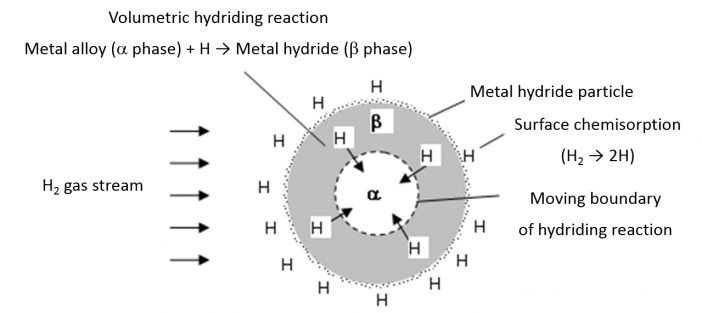
Figure 5: Schematic View of Hydrogen Dissociation at the Surface of Metal Hydride Particle and Volumetric Hydriding Reaction in Metal Hydride
For the temperature range around 65-80°C, Lanthanum based metal hydrides (e.g., LaNi5) or Calcium-Mischmetal based metal hydrides (e.g., Ca0.7Mm0.4Ni5) could be used, which offers adequate dissociation pressures, fast reaction, low hysteresis, and easy activation. Hydrogen dissociation pressures for these two hydride systems are shown in Table 1. Besides the commercial metal hydrides, numerous research materials are available that provide better performance, and can be tailored for particular applications.
Table 1. Hydrogen Pressure as a Function of Temperature for Two Hydrides
*Scroll right to view the table on mobile
| Hydride | -40°C | 70°C | 80°C |
| Ca0.7Mm0.3Ni5 | 2.5 psia | 216 psia | 282 psia |
| LaNi5 | 0.7 psia | 124 psia | 168 psia |
CONDUCTIVITY AND MULTIPLE HYDRIDING/DEHYDRIDING CYCLES
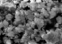
Figure 6: Scanning electron micrographs of nanocrystalline MgH2 metal hydride.
Conventional hydride materials with a polycrystalline structure have relatively low hydrogen/heat storage capacity by weight and relatively slow absorption/desorption kinetics. Substantial improvements in the hydriding/dehydriding properties of metal hydrides could possibly be achieved by the formation of nanocrystalline structures using non-equilibrium processing techniques such as mechanical alloying or high-energy ball-milling. It has been shown that nanocrystalline LaNi5 type metal hydrides lead to advanced nanocrystalline intermetallics representing a new generation of metal hydride materials with the following characteristics: high storage capacity, stable temperature-pressure cycling capacity during the lifetime of the system, low hysteresis, and good corrosion stability[1]. A scanning electron micrograph of another commonly used high-temperature metal hydride, MgH2, after ball milling is shown in 2[2]. The surface and morphology of Mg particles after milling were rough and irregular. SEM observation showed small catalyst particle clusters covering larger Mg particles after milling. The surface area and effective grain boundaries of Mg hydrides significantly increased, resulting in enhanced sorption kinetics by providing a greatly increased number of reactive sites during high-energy ball milling.
There are two factors that must be considered when using nanocrystalline hydrides. The first is low effective thermal conductivity. Typical hydride particles are generally small, to improve the reaction kinetics by minimizing the permeation length. Small particles, even if sintered, have a much lower thermal conductivity than the bulk material. Either high-conductivity fins or heat pipes are used to improve the thermal conductivity, in a similar fashion to PCM heat sinks.
In most metal hydrides undergoing hydriding/dehydriding cycles, high-volume strains lead to “decrepitation” (or pulverization) of metal hydrides into a powdered bed of micron-sized particles. The low thermal conductivity of such a powder bed (effective thermal conductivity = ~10-1 W/m-K) limits the heat transfer and, therefore, retards the apparent kinetics. ACT has used a metal hydride micro-encapsulation technique to coat the hydride powder particle with a thin (submicron size) copper layer using an electroless plating technique, as shown in Figure 3. This micro-encapsulation allows the decrepitated metal hydride particles to be contained inside a thin copper shell even after many hydriding/dehydriding cycles. Provided with a driving force, hydrogen readily diffuses through the thin copper layer. The micro-encapsulated technique can bring the hydride powder particle thermal conductivity up to ~3-5 W/m-K, which is a greater than 50 times improvement in effective thermal conductivity.

Figure 7: (a) Raw metal hydride powder (LaNi5), (b) copper-plated metal hydride powder, and (c) cross-sectional view of the copper-plated metal hydride particle.
ACT has developed a multiple-cycle hydride system, and is looking into single-use hydride venting systems:
- Single Use Hydride Venting Systems (One to a Few Cycles) offer a potential volume reduction of 90 percent or more when compared with PCM systems.
- Hydride Thermal Storage for Multiple Cycles (Dampening)
[1]. M. Jurczyk, L. Smardz, A. Szajek, “Nanocrystalline materials for Ni–MH batteries”, Materials Science and Engineering B108 (2004) 67–75
[2]. Chan-yeol Seo, Yeong Yoo and Zahir Dehouche, “Hydrogen sorption kinetics of nanocrystalline Mg-based composites using proton conductive ceramic catalysts”, Proceedings International Hydrogen Energy Congress and Exhibition IHEC 2005, Istanbul, Turkey, 13-15 July 2005
SINGLE-USE HYDRIDE VENTING SYSTEMS FOR THERMAL STORAGE (ONE TO A FEW CYCLES)
Similar to vapor venting thermal storage, hydride venting thermal storage offers the potential for lower mass and volume systems, when compared with conventional PCM thermal storage systems. Thermal storage is provided by the release of the absorbed hydrogen when heat is applied. Micro-encapsulated metal hydrides are capable of storing huge amounts of heat with rapid reaction kinetics. Metal hydrides have a superior volumetric heat storage capacity when compared to phase change materials. A commonly used metal hydride, LaNi5, has a theoretical heat storage capacity of 1200kJ/liter, while paraffin wax PCM material only has a heat storage capacity of 160-200kJ/liter. A greater heat storage density results in a more compact system with tighter temperature control.
ACT has already demonstrated a hydride thermal storage system for multiple cycles. In this system, the heat input released hydrogen from the metal hydride, which was then stored in a tank. A hydrogen compressor was then used to drive the hydrogen back into metal hydride to recharge the system. Unfortunately, the added mass of the tank and compressor (using current technology) made the system less competitive than a simple PCM heat sink.
However, theoretical calculations have shown that a vented hydride system has a very large reduction in volume when compared with a conventional PCM system. As shown in Table 1, a micro-encapsulated, vented hydride system would have one-half of the mass of a PCM system, but only 7% of the volume.
Comparison of Mass and Volume for PCM and Metal Hydride Venting Systems
| Stored Heat | System | Mass | Volume |
| 3 kW for 45 sec = 0.135 MJ | PCM | 1.5 kg | 2.0 liter |
| Metal Hydride | 0.78 kg | 0.13 liter | |
| 1 kW for 30 min = 1.8 MJ | PCM | 20.5 kg | 26.6 liter |
| Metal Hydride | 10.3 kg | 1.69 liter |
HYDRIDE THERMAL STORAGE FOR MULTIPLE CYCLES (DAMPENING)
ACT has been developing thermal storage technologies based on metal hydrides and phase change materials (PCM).
PCMs are traditional thermal storage materials because of their relative maturity. Metal hydrides are relatively new for thermal storage applications. The biggest advantage of metal hydrides is the volumetric heat capacity. For example, Ca0.2Mm0.8Ni5, a common metal hydride, has a heat capacity of 819.3 MJ/m3, while Rubitherm RT2, a common PCM, has a heat capacity of 177.5 MJ/m3. Metal hydrides for a wide range of operating temperatures are readily available from commercial sources.
Both metal hydrides and PCMs, in the form of raw materials, have very low thermal conductivities (on the order of 0.1W/m-K). This is a detriment to designing a compact thermal storage system. Metal fins or graphite foams are often used with PCMs to enhance heat transfer. For metal hydrides, ACT utilizes a “micro-encapsulation technique” to achieve a thermal conductivity of 5W/m-K or greater.
Figure 8. PCM in a heat storage container
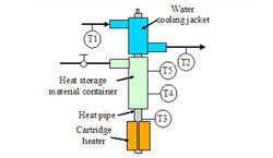
The figure to the left shows a prototype thermal storage test article that has a heat storage volume of 5cc. The test article consists of a heat pipe, a heat storage material container, and a water-cooling jacket. A cartridge heater is attached to the heat pipe evaporator to provide heat input. The test article is insulated from the ambient to minimize heat loss during testing.
Figure 9. Prototype thermal storage test
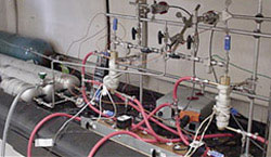
Two test articles of identical dimensions were fabricated and tested at the same conditions. One of the articles used a metal hydride and the other used a PCM in the heat storage container. To the right is a photo of the test setup.
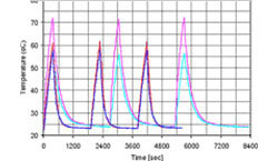
Figure 10. Temperature measurements
Figure 10 above shows the temperature measurements for both devices (pink color for the PCM device and blue color for the metal hydride device). The heat input was cycled between 0 and 15W, with the 15W input maintained for 370 seconds during each cycle. The cooling water was turned off during heat storage and on during regeneration. The metal hydride device was able to absorb the heat input and maintain the heat source at a lower temperature than the PCM device. The metal hydride device also regenerated more quickly than the PCM device.


- thermal storage with venting
- Comparison of Mass and Volume for PCM, Methanol Venting, and Hydride Venting Systems
- SINGLE-USE VAPOR VENTING SYSTEMS FOR THERMAL STORAGE (ONE TO A FEW CYCLES)
- Comparison of Mass and Volume for PCM and Methanol Venting Systems
- Vapor-vented thermal storage system Applications
- VAPOR VENTING- Comet Sample Return
- HYDRIDE THERMAL STORAGE
- SINGLE-USE HYDRIDE VENTING SYSTEMS FOR THERMAL STORAGE (ONE TO A FEW CYCLES)
- Comparison of Mass and Volume for PCM and Metal Hydride Venting Systems
- HYDRIDE THERMAL STORAGE FOR MULTIPLE CYCLES (DAMPENING)

