
SPACECRAFT THERMAL CONTROL
Deployable Radiators
Following the trend of increased power density in electronics, small satellites such as CubeSats are facing an increase in power and waste heat, which necessitates the development of improved thermal management systems. Given the reduced size and weight requirements of satellites, deployable radiators provide a unique solution where the radiator can be held compact during launch, and deployed for use once in orbit, expanding the heat rejection capabilities of the thermal management system. ACT has developed two methods of deploying radiators while maintaining a strong thermal connection to the body of the satellite. The first uses pressure from the working fluid within the thermal management system to expand a curved radiator panel, making the view factor and therefore performance of the radiator variable and controlled based on the heat load of the system.
Publications:
Lunar Night Survival- Thermal Switch
ACT has developed a two-phase thermal switch that utilizes a sealed, metal bellows containing a saturated working fluid. The bellows can expand, or contract based on the vapor pressure of the working fluid. One end of the bellows is fixed to a heat source, and the bellows is designed to expand when heated to connect with a heat sink at a fixed temperature set-point. When the bellows are in contact with the heat sink, the switch is “on”, and conversely when the bellows are detached, the switch is “off”. With proper design, larger On/Off conductance ratios can be achieved. In certain modes of operation, the thermal switch can also act as a variable conductance device through intermittent contact with the heat sink. This type of variable control is ideal for use in environments that undergo extreme temperature changes, such as a rover experiencing both Lunar Day and Lunar Night.
Publications:
- Van Velson, N., Diebold, J., Schulze, D-P., Tarau, C., & Anderson, W.G. (2023). Two-Phase Thermal Switch for Lunar Lander and Rover Thermal Management. 52nd International Conference on Environmental Systems (ICES), Calgary, Canada, July 16-20.
- Van Velson, N., Tarau, C., & Anderson, W. G. (2015, July). Two-Phase Thermal Switch for Spacecraft Passive Thermal Management. 45th International Conference on Environmental Systems (ICES), Bellevue, WA, July 12-16.
Energy
Swiss-Roll Advanced Combustor
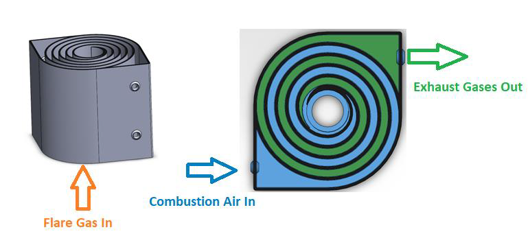
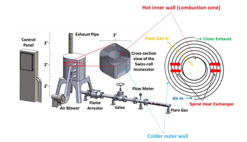
The ‘Swiss roll’ combustor is a unique device that integrates heat recovery with chemical reaction by wrapping the combustion zone around a spiral counterflow heat exchanger. The heat of combustion from the hot products is transferred to the incoming air (without mass transfer) resulting in a super-adiabatic reaction temperature at the center. This elevated reaction temperature can enable a stable, near-equilibrium reaction even with low heating value reactant streams. In other words, the excess enthalpy reaction extends the flammability limits of the fuel and enables ultra-lean, self-sustained combustion, eliminating the supplemental fuel that would otherwise be needed to incinerate low-BTU waste gas streams. Extensive experimental work and modeling have been performed to understand the effect of heat recuperation on the chemical reaction and parametric design optimization. Novel additive manufacturing methods with various high-temperature materials are currently being used to manufacture a wide range of scale Swiss-roll combustors. The Swiss-roll combustor can be applied for emissions control in oil and gas, chemical, process, and biogas industries.
Publications:
- Crawmer, J.; Chen, C.; Richard, B.; Pearlman, H.; Edwards, T.; Ronney, P. An Innovative Volatile Organic Compound Incinerator. International Conference on Thermal Treatment Technologies & Hazardous Waste Combustors, 2018, IT3-22.
- Adhikari, D.; Bhuripanyo, P.; Rao, P.; Radyjowski, P.; Chen, C.,; Ronney, P.; “Swiss-roll Combustor: An Innovative Enclosed Combustor for high Methane Destruction Efficiency and Ultra-low NOX Emissions,” American Flame Research Committee Industrial Combustion Symposium, 2023
- Radyjowski, P.; Bhuripanyo, P.; Chen, C.; Ronney, P.; “Swiss-roll Autothermal Ammonia Reformer for Gas Turbine Applications,” American Flame Research Committee Industrial Combustion Symposium, 2023
Swiss Roll FAQ’s

Developed by ACT, the Swiss-roll combustor is a unique, patented burner that uses efficient heat recuperation to reduce both supplemental fuel consumption and emissions by directly integrating the combustion zone inside a heat exchanger. By locating combustor inside the heat exchanger, most of the heat from combustion products can be recovered leading to very high thermal and combustion efficiencies.
Moreover, unlike conventional flares that operate diffusion flame, the SRC operates an ultra-lean premixed flame which enables burning both low and high BTU gases while maintaining high destruction efficiency and low NOx and CO emissions.
- Crude oil and gas tank batteries
- Upstream oil and gas
- Landfill gases and biogases
- Manure management in dairy farms
- Agriculture and food processing
During normal operation, the flare gas enters the center of the swiss-roll combustor, while combustion air enters via the inlet swirl channel where it is preheated to increase its enthalpy. The products of combustion exit via the outlet swirl channels. With excess enthalpy, the combustion is self-sustained in the center of the Swiss-roll at super-adiabatic conditions for a given equivalence ratio. A control system is used to control the air flow rate from the blower to optimize combustion. The required airflow rate is determined by the control system with inputs from flare gas flow rate, pressure, and combustor temperatures.
| Features | Benefits |
| High reaction temperature | Near 100% combustion efficiency |
| Low NOx emissions | Can meet current NOX and CO regulatory requirements |
| Fully enclosed combustor | No smoke or no visible flame – clear exhaust gas
|
| Can handle low and high BTU gases | Reduced supplementary fuel consumption |
| Forced draft operation | No effect of cross wind; Easy startup |
| High turn down ratio | Wide operation range for both flow rate and composition • High destruction efficiency over wide operational range |
|
|
| No air or steam assist required | Lower utility costs |
Typically, an EGF requires natural draft for combustion air while the swiss-roll combustor utilizes forced draft via a blower.
- For the same capacity, the SRC stack is smaller than an EGF. This leads to faster
construction and lower capital costs. - The SRC requires lesser refractory liner material compared to an EGF.
- There is no temperature control in an EGF, per se. Because it is driven by natural draft
and no stack damper exists, the amount of excess combustion air entering the
combustion chamber cannot be controlled. On the other hand, since the SRC used a
forced draft fan, combustion/excess air and hence emissions can be finely controlled.
A small amount of supplementary fuel is required at startup to attain super-adiabatic conditions inside the Swiss-roll combustor. Once this condition is attained, additional supplementary fuel is not required for continuous steady-state operation.
For most of the time, the Swiss-roll operates in the lean to ultra-lean combustion mode with H2O and CO2 at the exhaust. In the situation where there is a large spike in flare gas flow rate, the SRC may switch to the rich combustion mode in which the high-quality syngas will be generated. The high-quality syngas is easily flared out (to H2O and CO2) without generating any sooty flame that has a high thermal radiation impact.
Currently, a single Swiss-roll combustor can flare 100,000 SCF/day (70 SCFM). However, depending upon the available vent gas pressure, several Swiss-roll combustors can be
operated in parallel to increase the overall capacity.
The Swiss-roll combustor-based flare system requires components such as knockout drum, safety valve, flow meters, flame arrestor, and control system. This equipment overlaps with equipment for conventional air and steam assisted flare systems. A fan/blower is also required to provide air for combustion. Therefore, it can be installed seamlessly with existing flare infrastructure.
High Temperature – High Power Heat Pipes
High-temperature heat pipes refer to heat pipes designed to operate above 400°C. Above this temperature heat pipes must use alkali metals such as cesium, potassium, NaK, sodium, or lithium as the working fluid. Heat pipe envelope material selection requires careful consideration of chemical compatibility with the working fluid, high-temperature structural properties, and the potentially corrosive nature of the environment in which the heat pipe is applied. ACT’s R&D Department has extensive experience developing unique high-temperature heat pipes for various applications. Examples of ongoing and past R&D high-temperature programs include:
- Superalloy and refractory metal-alkali metal heat pipes for nuclear reactor heat extraction
- High-temperature waste heat recovery
- Variable conductance sodium heat pipes for backup cooling for Stirling convertors
- Alkali metal diode heat pipes for a Venus lander thermal management system
- Pressure-controlled alkali metal heat pipes for lunar regolith oxygen production
Publications:
- Beard, D., Tarau, C., and Anderson, W. “Sodium Heat Pipes for Spacecraft Fission Power Generation,” AIAA Propulsion and Energy Forum and Exposition, 2017.
- Anderson, W., Beard, D., and Tarau, C., “Self-Venting Arterial Heat Pipes for Spacecraft Applications,” Joint 18th International Heat Pipe Conference and 12th International Heat Pipe Symposium, 2016.
- Schmidt, J. and Ababneh, “Heat Pipe Embedded Thermoelectric Generator for Diesel Generator Set Waste Heat Recovery,” 14th International Energy Conversion Engineering Conference, 2016
- Tarau, C., Schwendeman, C., Schifer, N., and Anderson, W., “Optimized Heat Pipe Backup Cooling System Tested with a Stirling Convertor,” 13th International Energy Conversion Engineering Conference, 2015
- Tarau, C., DeChristopher, M., and Anderson, W., “Diode Heat Pipes for Long-Lived Venus Landers,” 10th International Energy Conversion Engineering Conference, 2012
- Hartenstine, J., Walker, K., Tarau, C., and Anderson, W., “Pressure Controlled Heat Pipe Solar Receiver for Regolith Oxygen Production with Multiple Reactors,” 49th AIAA Aerospace Sciences Meeting, AIAA 2011-611.
Furnace Cooling
Fundamental research in extreme temperature environments is essential for various scientific and industrial applications. The need for advanced characterization techniques, such as neutron scattering, is essential to study materials under extreme conditions. These conditions, often reaching temperatures as high as 1700 °C, are relevant in fields such as materials science, metallurgy, chemical reaction kinetics, condensed matter physics, and much more. With such wide applications, there is a large demand for high-temperature neutron experiments at large facilities such as Oak Ridge National Laboratory (ORNL). However, due to the limited neutron resources, most facilities remain overbooked and have lengthy wait lists for users to run experiments. One of the primary challenges faced in high-temperature neutron furnaces is the time-consuming cooldown of the test furnace. The vacuum environment in these furnaces lead to slow radiative cooling rates, especially when cooling from 1000 °C to 100 °C. The substantial cooldown time at these temperatures can take 2-3 times longer than the actual experiment itself, causing a significant waste of valuable neutron beam time and limiting the number of experiments possible.
Advanced Cooling Technologies, Inc. (ACT) has developed a groundbreaking cooling technology that addresses this challenge. This advanced cooling system circulates a neutron-friendly gas through the internal furnace body and onto the sample, dramatically reducing the cooldown time by a factor of 30. This significantly enhances the throughput of neutron experiments, allowing users to perform more experiments in the same amount of time.
Download the cut sheet here.
CO2 Capture
ACT, in partnership with Lehigh University, has developed a novel acid/base ion-exchange direct air capture (DAC) system that can utilize either a low-grade heat source medium or an electrically derived weak base solution to regenerate the capture sorbent. This DAC sorbent has demonstrated CO₂ capture rates of greater than 90% with thermal regeneration of the sorbet shown to release captured CO₂ at temperatures as low as 50 °C with over 90% of the CO₂ released at a temperature of 100 °C. This novel system uses widely available commercial adsorbent resins, which reduce cost and alleviate supply constraints. Additionally, the system design is easily scalable and can be implemented as a modular system to minimize manufacturing and deployment costs.
Read: Market-ready thermal energy storage system for decarbonization applications
Plasma
Plasma Sterilization – Medical Equipment
Ethylene Oxide (EtO) is the most common method of sterilant used in medical equipment facilities because it is universally effective on any medical equipment containing heat-sensitive polymers and/or having high aspect ratios, like long lumens. However, due to the high cost of EtO, high toxicity, and the length of time it takes to perform sterilization using this method, the FDA SBIR program is funding research to develop alternative sterilization solutions. ACT and Rutgers University have identified an ozone plasma sterilization system with plasma-in-lumen technology (Figure 1) to be one innovative alternative solution offering many improvements over EtO. Compared to other low-temperature sterilization approaches such as Vaporous Hydrogen Peroxide (VHP), ACT’s technology can sterilize lumens with arbitrary lengths.
Plasma-Powder De-Oxidation
Plasma, the fourth state of matter, is a highly reactive state that can be used to enhance or assist various chemical processes. Low-temperature plasma (LTP) creates a set of circumstances that enable chemical reactions without the adverse effects of material decomposition, melting, agglomeration, or sintering. One such chemical reaction is the reduction of metal oxides to form metal and water (MxOy → M+ H2O). Metal particles are used in a host of applications including energetic materials and 3D printing (i.e., additive manufacturing). When used (or even stored or transported) for these applications, the inherently thin layer of metal oxide on each particle surface grows, thereby changing the chemical and mechanical properties of the powders and any macro-scale parts manufactured from those powders. ACT is currently developing an LTP process that can reduce metal oxides from metal powders. Oxide content can be reduced as a pre-treatment prior to utilization/fabrication processes or as a post-treatment recycling process afterward. Oxides can be removed from metals and metalloids including copper, aluminum, steel, nickel alloys, and boron. If desired, ACT can also apply a plasma-enhanced chemical vapor deposition (PECVD) technique immediately after the LTP metal oxide reduction to passivate the reduced oxide particles. This PECVD passivation layer protects the particles from reoxidation during transport and storage in ambient conditions.
Publications:
- 1. P. Agrawal, D. Jensen, C.-H. Chen, R. M. Rioux, T. Matsoukas. “Surface-functionalized Boron Nanoparticles with Reduced Oxide Content by Non-thermal Plasma Processing for Nanoenergetic Applications.” ACS Appl. Mater. Interf. 13 (2021) 6844-6855.
- Dency, M. A.; Kintzer, J.; Schmitt, T.; Troop, G.; Balkhandia, P.; Chen, Chien-Hua; Jensen, D. Nonthermal Hydrogen Plasma Process for the Reuse of Metal Additive Manufacturing Feedstock Powder. Ind. Eng. Chem. Res. 2024, 63, 21890–21900.
Advanced Modeling
Peridynamics-Based Meshless Modeling
Peridynamics (PD) is a recently introduced non-local reformulation of classical elasticity theory for modeling materials with discontinuities such as cracks [1]. The theory replaces the partial differential equations of classical solid mechanics with integro-differential equations. The equations are based on a model which treats the internal forces within a body as a network of interactions between material points. The governing equation for the peridynamics material points is given by the local conservation of linear momentum as,
The numerical discretization of the governing equation can be cast into a meshless particle (Lagrangian-type) approach, which allows for simulation of discontinuities like crack without any need for re-meshing the domain. The mathematical structure of the PD approach automatically enables simulation of cracks propagation and failure, without the need for complicated crack path algorithms like that of XFEM or cohesive element method.
PD framework can also be used to model multiphysics problems, by expanding the constitutive model to include thermal, electrical, and diffusive effects. ACT has developed PD based models for prediction of damage phenomenon in the following areas:
1. Corrosion fatigue damage in metals
2. Progressive damage in thick composites
3. Crack propagation and failure in engineering metals and alloys
Peridynamics is very well suited to mode damage and crack paths in fiber reinforced composites (FRCs). Composites exhibit complex failure mechanisms due to their inherent anisotropy (fiber, matrix phases) and damage aspects like matrix cracking, fiber breakage, fiber-matrix shear and delamination. The exact nature of damage evolution and failure depends on complex interactions between the fiber, matrix phases of each ply and inter-ply interactions, in response to the loading environment.
Publications:
- S. Rokkam, M. Gunzburger, M. Brothers, N. Phan, K. Goel, “A nonlocal peridynamics modeling approach for corrosion damage and crack propagation”, Theoretical and Applied Fracture Mechanics, Volume 101, 2019, Pages 373-387, ISSN 0167-8442, https://doi.org/10.1016/j.tafmec.2019.03.010. https://www.sciencedirect.com/science/article/pii/S0167844218305950
- S. Rokkam, Q. Truong and M. Gunzburger, “Meshless Computational Tools for Damage and Failure Modeling,” 2018 17th IEEE Intersociety Conference on Thermal and Thermomechanical Phenomena in Electronic Systems (ITherm), San Diego, CA, USA, 2018, pp. 1155-1159, doi: 10.1109/ITHERM.2018.8419543. https://ieeexplore.ieee.org/abstract/document/8419543/
- S. Rokkam, N. Phan, M. Gunzburger, S. Shanbhag, K. Goel, “Meshless Peridynamics Method for Modeling Corrosion Crack Propagation”, 6th International Conference on Crack Paths (CP 2018), Verona, Italy, 19-21 September 2018. https://www.1-act.com/wp-content/uploads/2018/10/Meshless-Peridynamics-Corrosion-Crack.pdf
- S. K. Rokkam, Q. Truong, M. Gunzburger, K. Goel, “A Peridynamics-FEM Approach for Crack Path Prediction in Fiber-Reinforced Composites”, AIAA 2018-0651 Session: Fatigue and Fracture I, Jan 2018. https://doi.org/10.2514/6.2018-0651
Corrosion Damage and Corrosion Fatigue
Corrosion and its synergistic interactions with mechanical loading are a major cause of damage and failure of structural components in aging Navy aircraft fleet and infrastructure, with adverse implications on both operational safety and ownership costs. Traditional tools for predicting corrosion-related damage are based on analytical models and yield large uncertainties in service environments.
ACT developed a micro-chemically sensitive peridynamics model for corrosion damage and resulting crack propagation phenomena under synergistic effects of corrosion and mechanical loading. The approach is based on nonlocal peridynamics theory that replaces governing equations of classical continuum mechanics with integro-differential equations that are easy to solve across discontinuities like cracks. The framework is able to capture corrosion pitting, nucleation, crack path propagation under synergistic influence of corrosion and mechanical loading, without the need to re-mesh the domain or special numerical treatments. The developed peridynamic approach provides a physics-based alternative to conventional theories and enables crack propagation studies in corrosive environments. The approach is capable of modeling stress corrosion cracking (SCC), Hydrogen Embrittlement (H-Embrittlement), Corrosion Fatigue (CF).
The resulting corrosion toolkit provides a physics-based framework for modeling corrosion influence on naval aircraft components and its impact to service life.
Publications:
- S. Rokkam, M. Gunzburger, M. Brothers, N. Phan, K. Goel, “A nonlocal peridynamics modeling approach for corrosion damage and crack propagation”, Theoretical and Applied Fracture Mechanics, Volume 101, 2019, Pages 373-387, ISSN 0167-8442, https://doi.org/10.1016/j.tafmec.2019.03.010. https://www.sciencedirect.com/science/article/pii/S0167844218305950
- E. Lees, S. Rokkam, S. Shanbhag, M. Gunzburger, “The electroneutrality constraint in nonlocal models”, The Journal of Chemical Physics, Volume 147, Issue 12, 2017. https://pubs.aip.org/aip/jcp/article/147/12/124102/1003817
- S. Rokkam, N. Phan, M. Gunzburger, S. Shanbhag, K. Goel, “Meshless Peridynamics Method for Modeling Corrosion Crack Propagation”, 6th International Conference on Crack Paths (CP 2018), Verona, Italy, 19-21 September 2018. https://www.1-act.com/wp-content/uploads/2018/10/Meshless-Peridynamics-Corrosion-Crack.pdf
Molecular Dynamics for Nano-scale Phenomena
Molecular Dynamics (MD) is an advanced simulation method where the trajectories of atoms are tracked as they move about due to the attractive and repulsive forces between neighboring atoms. Using interatomic potentials that describe the forces between atoms, Newton’s Second Law of Motion, and subjecting the ensemble of atoms to the desired temperature and pressure, the trajectories are computed by numerical integration of the equations of motion. Based on these calculated trajectories, transport properties, structural characteristics and reaction pathways can be predicted for various materials, liquids and gas mixtures. Using modern computing processors and parallel processing techniques, MD simulations can calculate systems with millions of atoms, large enough to model complex material systems and chemical reactions, for time periods up to 10′s of nanoseconds, long enough to calculate time-averaged transport properties and kinetics.
Using molecular dynamics simulations with a reactive force field (ReaxFF), ACT team generated models of amorphous carbon (a-C) at a wide range of densities (from 0.5 g/cc to 3.2 g/cc) via the ‘liquid-quench’ method. A systematic study is undertaken to characterize the structural features of the resulting a-C models as a function of carbon density and liquid quench simulation conditions: quench rate, type of quench (linear or exponential), annealing time and size of simulation box. The resulting char structures were subsequently.
Publications:
- Tapan G. Desai, Gota Kikugawa, et al., “Effect of Crosslink Formation on Heat Conduction in Amorphous Polymers”, Journal of Applied Physics 114, published online July 16, 2013 https://www.1-act.com/effect-of-crosslink-formation-on-heat-conduction-in-amorphous-polymers/
- R. Ranganathan, S. Rokkam, T. Desai, P. Keblinski, Generation of amorphous carbon models using liquid quench method: A reactive molecular dynamics study, Carbon, Volume 113, 2017, Pages 87-99, ISSN 0008-6223, https://doi.org/10.1016/j.carbon.2016.11.024. https://www.sciencedirect.com/science/article/pii/S0008622316309988
- R. Ranganathan, S. Rokkam, T. Desai, P. Keblinski, P. Cross, R. Burns, “ Modeling high-temperature diffusion of gases in micro and mesoporous amorphous carbon”, The Journal of Chemical Physics, Volume 143, Issue 8, August 2015. https://doi.org/10.1063/1.4928633
Electro-Thermal for Semiconductors
As transistor sizes continue to decrease, thermal engineers are investigating ways to decouple the electron and phonon transport physics that are typically combined in the classical Fourier’s Law of Conduction. At the various semiconductor/metallic interfaces, heat traveling in the phonons in the semiconductor material must first conduct heat to the phonons in the metal. The phonons in the metal must then transfer heat to the electrons in the metal. These extra transport steps add additional resistances that are not present if only contact resistance and Fourier-type conduction are included. MD, ab initio and other advanced modeling techniques can be used to estimate the atomic structure at the interface and the “bottlenecks” that occur when conducting between phonons and electrons at the interface between two materials.
Electronics cooling is currently one of the largest areas for thermal research and development. The decreasing size and increasing power consumption in transistors have led to many thermal challenges. MD, ab initio and BTE modeling techniques are required to accurately predict the chip-level thermal transport process. Accurate modeling of the electron conduction, phonon conduction, and energy transfer between electrons and phonons is required to capture the heating process in a transistor. This technical understanding is important since the relative proportions of electron conduction, phonon conduction and electron to phonon conversion are important.
ACT has developed several in-house models and simulation codes to successfully simulate multiphysics behavior in semiconductor materials made of SiC and GaN. These tools enable simulation of coupled field problems and provide previously unavailable insights to materials and thermal engineers involved in semiconductor chip design.
Publications:
Reactive Molecular Dynamics and Accelerated Techniques for Computational Chemistry
Reactive molecular dynamics methods refer to a class of MD methods that enable the simulation of chemical reactions and chemistry-based nanoscale phenomena with accuracy to ab initio methods. While classical MD provides a powerful tool to simulate nanoscale spatiotemporal phenomena and bulk properties, they lack the ability to simulate chemical reactions. On the other hand, quantum mechanics (QM) based ab initio methods enable simulations of chemical reactions but are computationally expensive and limited to a 10’s of atoms. To circumvent this problem, reactive MD methods have been developed that use empirical interatomic potentials with the capability to locally mimic the quantum effects of a bond change due to chemical reactions.
Reactive MD methods use a force field description which is ‘trained’ to reproduce reactions determined from quantum mechanical calculations and experimental data. A class of such methods uses concept of bond order to represent the forces between interacting atoms in a chemical system. Typical examples of such force descriptions include Reactive Empirical Bond-Order potential (REBO), Adaptive Intermolecular Reactive Empirical Bond-Order potential (AIREBO), Reactive Force Field (ReaxFF) potential. The bond order-based definition of atomic and molecular interactions excludes the need for predefined reactive sites and allows for dynamic description of bond breaking and formation. Recent progress in reactive potentials enables study of wide range of materials such as hydrocarbons, polymers, silica systems, nitramines and catalysis phenomena.
ACT has developed a reactive MD-based computational framework to investigate chemical behavior of polymer composite materials subject to thermo-chemical degradation. The approach makes use of reactive MD simulations and novel reactive force fields to obtain information on chemical products, rate of formation of these products and reaction pathways. The framework has been developed and applied to study pyrolysis (thermal deposition) phenomena for two types of materials: (i) ablative phenolic heat-shield composite used in space-craft reentry vehicles, and (ii) ablative rubber insulator of solid rocket motor type engines.
Accelerated Reactive Molecular Dynamics Simulation Framework
Conventional reactive MD methods are limited to high temperature simulations and suffer from small timestep problem inherent to MD (due to stiffness of evolution equations). Simulation temperatures of reactive MD studies are usually performed at temperatures of ~3000K with timestep of order of 0.25 femtoseconds. Consequently, simulations can probe 100’s of picosecond of dynamics to a maximum of a nanosecond. However, most interesting phenomena at nanoscale evolve over longer times and sometimes requires lower temperature studies. To address these challenges, ACT has recently developed Accelerated Reactive Molecular Dynamics Simulator (ARMS), a computational tool which can be used to investigate material chemistry at low temperatures using reactive molecular dynamics simulation. The framework makes use of multi-core processors to track many replicas of the system in parallel, effectively parallelizing the time required to simulate chemical reactions at low temperature. The methodology has been used to probe low temperature (of ~1750K) pyrolysis chemistry of ablative heat-shield materials typical to space-craft re-entry vehicles and solid rocket motor insulation. We find that the chemistry at low-temperature is significantly different from high temperatures and results in distinct reaction pathways.
ACT’s custom tools for Chemical Kinetics of Complex Phenomena
To enable molecular modeling of complex chemical phenomena resulting from multiple active species and long-chain polymers is limited by uncertainties in the reaction rate parameters, which increase rapidly with the number of active species and/or reaction pathways. Reactive molecular dynamics simulations have the potential to help obtain in-depth information on the chemical reactions that occur between the polymer (e.g., ablative material) and the multiple active species in an aggressive environment. ACT team developed two custom tools that post-processes reactive MD simulation data and enables the identification of chemical kinetics data and reduced models of chemical kinetics.
1. Molecular Fraction Analysis Custom Toolkit (MolfrACT) – for extracting chemical species, reaction pathways and energetics information.
2. Kinetic Analysis Custom Toolkit (KinACT) – tools for reduction of chemical kinetics data to obtain reduced chemical kinetics.
The reaction-related information is extracted via an iterative scheme christened CReSIS (Consistent Reaction Stoichiometry via an Iterative Scheme). The framework was validated by simulating iso-octane combustion and comparing against experimentally reported pathways for iso-octane combustion. Subsequently, the framework was employed to investigate ablation chemistry of ethylene-propylene-diene-monomer (EPDM) rubber ablatives.
Publications:
- K. Sasikumar, R. Ranganathan, S. Rokkam, T. Desai, R. Burnes, P. Cross, “Development of chemical kinetics models from atomistic reactive molecular dynamics simulations: application to iso-octane combustion and rubber ablative degradation”, The Journal of Physical Chemistry A, Volume 126, Issue 21, Pages 3358-3372, 2022. https://pubs.acs.org/doi/abs/10.1021/acs.jpca.2c00901
- R. Ranganathan, S. Rokkam, T. Desai, P. Keblinski, Generation of amorphous carbon models using liquid quench method: A reactive molecular dynamics study, Carbon, Volume 113, 2017, Pages 87-99, ISSN 0008-6223, https://doi.org/10.1016/j.carbon.2016.11.024. https://www.sciencedirect.com/science/article/pii/S0008622316309988
Smooth Particle Hydrodynamics for Process Modeling
ACT developed a meshless approach that utilizes Smoothed Particle Hydrodynamics (SPH) to obtain a physics-based model capable of capturing the thermo-mechanical behavior of Linear Friction Welding (LFW) process in 3D. Linear friction welding (LFW) is a solid-state joining process in which a weld between two metals is formed by the combined action of heating via plastic deformation and forming force that creates a weld interface. The technique is increasingly attracting attention in aerospace industry, due its several advantages like absence of solidification defects, no requirement for external heat source, and the mechanical and fatigue properties of the weld being equivalent or surpassing the parent material. Due to large deformation, commercially available software tools are limited to modeling of LFW in 2D using Finite Element Method (FEM) with adaptive mesh controls. The developed models were employed to simulate and investigate flash formation and burn-off distance of LFW of Ti-6Al-4V workpieces. The SPH simulation results agreed well with FE simulation and experimental data.
Publications: